Why an electrical isolation diagram improves your medical device design
If you’re reading this, chances are you have a great idea for a medical device and you’re starting your design. You probably have an electrical element to your design. As tempting as it is to start ordering parts and tinkering, there are a few preliminary documents you can create to help you choose the right parts. Eventually you’ll need a design that must pass the requirements of IEC 60601-1.
Drafting documents now will prompt you to ask the right questions early and hopefully solve any core technology safety related hurdles early. The documents I discuss below are in addition to the standard risk management, requirements, specification, and architecture documents. They may even be design inputs, depending on the device you’re designing.
These (Preliminary, Draft) documents may include:
- Electrical Isolation/Insulation Strategy/Diagram
- Wiring Diagram
- Technology specific reports:
- e.g. Optical Safety Report
- Thermal Safety Report
StarFish Medical is approached by many companies with prototype devices in different stages of development. A somewhat common issue is that the design needs changes to varying degrees in order to satisfy electrical protection requirements for the patient. These requirements are often overlooked in design. It is not always sufficient just to include an IEC 60601 approved power supply or transformer, especially for devices with complex patient interfaces with multiple applied parts. Preparing an electrical insulation diagram can help identify the points in the system architecture where protection needs to be added.
An electrical insulation diagram should:
- Be kept simple
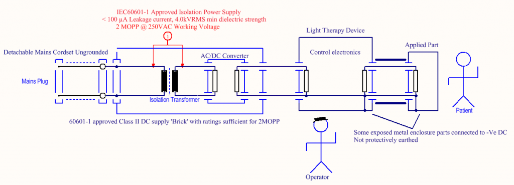
- Communicate where the Means of Operator (MOOP) and Means of Patient Protection (MOPP) are located in the design
- Identify what is considered the patient environment and any additional information that would be useful for someone to familiarize themselves with your design
- Aggregate any blocks of electronics that have equivalent insulation or safety-related compartmentalization into a single load. See point 1)
- Use symbols found in the IEC60601-1 standard when constructing our diagrams; refer to IEC60601-1 Annex J for some examples.
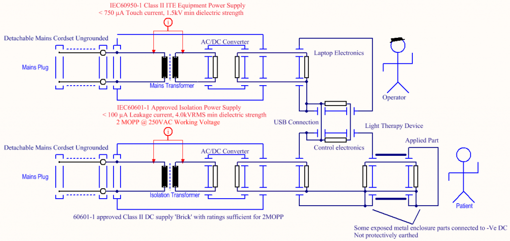
Standardized connections to displays, mains-powered devices, or the ubiquitous USB charging connector can circumvent MOPP. It is crucial to identify these points early to design the applied parts correctly and place insulation appropriately. It might prompt the designer to move MOPP closer to the applied part or identify convenient points along a signal chain to insert MOPP.

Here’s an example: a hand-held, light-based therapy device with an applied part is powered via an IEC 60601 AC to DC power brick with protections sufficient to be considered for 2 MOPP. As long as the rest of the device is designed appropriately, the electrical insulation strategy in the below diagram should be sufficient for maintaining electrical safety. Although the diagram below is lacking all of the aforementioned elements, it is sufficient for a preliminary strategy.
Now, let’s say that the product requirements have changed and there is a need for control via a USB connection and a laptop while the device is in use.

You update your insulation diagram and find that your MOPP have been circumvented by a class II power adapter that is IEC60950 rated (general information electronics). You use your updated diagram to show the team what this issue is and how patient safety can be maintained.
You then identify mitigations with the team such as adding a wireless connection, isolating the USB port, further insulating the applied part, etc. If the laptop must remain in the patient environment, different strategies would be explored.
Creating an insulation diagram early, referencing it in your system architecture document, and updating it during development will reduce the chance that a design change compromises patient safety. This is one simple example of a situation that is best identified early and planned for, as opposed to making a late fix that negatively impacts the design.
Christian Proch-McMechan is Principal Electrical Engineer at StarFish Medical.
Illustration: StarFish Medical
