This article is about the parasitic properties of capacitors. It discusses the issues they cause, mitigating the parasitic properties, and even how to turn them into something useful.
Note: This article assumes an understanding of basic circuit theory. In particular, it assumes knowledge of the behaviour of ideal capacitors, resistors, and inductors.
Basic Parasitic Properties
Remember that not all capacitors (even if of the same value) are created equal. There are several ways to model a capacitor’s non-ideal properties. In general, series resistance (RESR) and series inductance (LESL) are included.
When modelling parasitic properties of capacitors, parallel resistance (often referred to as RLeakage) and even parallel capacitance are often included. This article will focus primarily on the effects of series and leakage inductance and how to mitigate their undesirable effects.
Self-Resonant Frequency
All capacitors have a self-resonant frequency (can be denoted as fres) at which the capacitive reactance and parasitic inductive reactance cancel each other out. There is a point where the reactance of LESL cancels out the reactance of the ideal capacitance. This is made evident if we review the formulas for capacitive and inductive reactance:
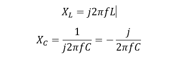
At the resonant frequency,

We can then solve for the resonant frequency:
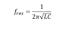
The graph[1] below illustrates what happens when you reach the resonant frequency and then exceed it. The 10 µF capacitor (with impedance plotted by the blue line) reaches its minimum impedance at around 2 kHz (which in this case, is the self-resonant frequency).
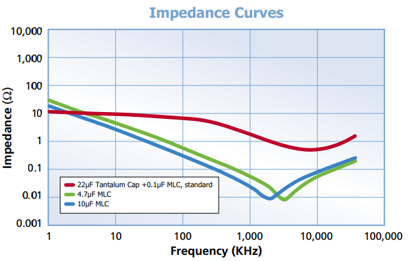
Not all datasheets will explicitly state a capacitor’s equivalent series resistance (ESR), equivalent series inductance (ESL) or self-resonant frequency. They will, however, often publish a graph similar to the one above.
Package
The physical size and shape of the package have an impact on the parasitic properties of your cap. I recommend always remembering the following:
- The leads of through-hole components introduce additional series inductance
- Physically larger components typically have higher series inductance
- 0603s have more favourable inductance than 0805s and 0402s have more favourable inductance than 0603s.
Three-terminal capacitors
Three-terminal capacitors can be used to change the effect of parasitic inductance. A three-terminal capacitor has two leads on one side. If the one-terminal side is connected to ground and the other two are the input and output of a signal respectively, you have an equivalent circuit like the one below.[2]
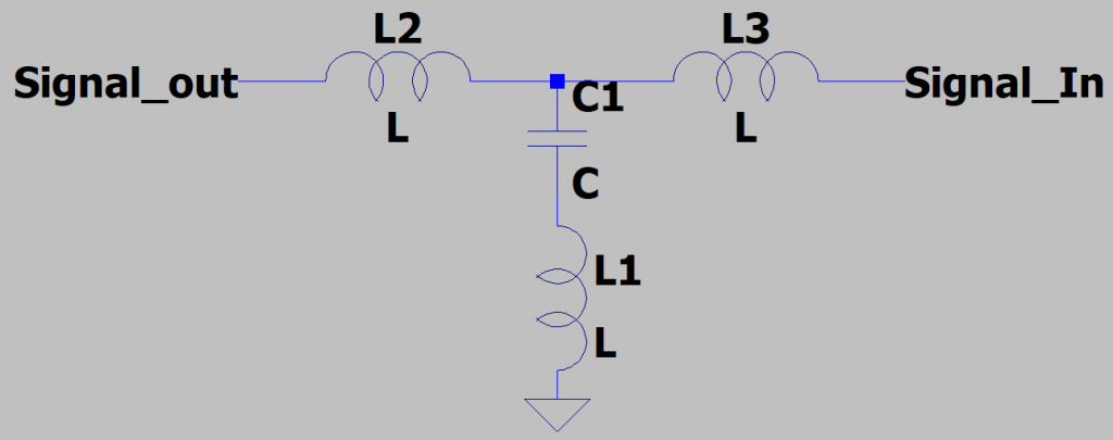
In this way, the inductances of L2 and L3 form a T-filter with the capacitance. This construction puts the parasitic inductance to use. This can increase the useful bandwidth of the capacitor dramatically.
Filtering a wide bandwidth of frequencies with decoupling caps
There are two main schools of thought on how to design a bank of decoupling capacitors that must filter a broad range of frequencies.
Big Capacitors in Parallel with Small Capacitors
One way of addressing this problem is by using one or more large capacitors in parallel with one or more small ones. The larger capacitors will be effective for filtering the lower frequency noise. The smaller capacitors (which can use a smaller package size, thereby allowing for smaller parasitic inductance) can filter out the higher frequencies.
Many Identical Capacitors in Parallel with Each other
A second common approach is to use a large number of low-inductance capacitors in parallel with each other of the same value. This mitigates ESR and LSR while still increasing the capacitance.
Simulate with the parasitic properties accounted for
Whichever of the above approaches you take, you should simulate your circuit accounting for the capacitor’s parasitic properties. This will provide valuable insight into how well different frequencies are filtered, where the resonant peak is, and how big it is.
Considerations for Switching Power Supplies
Remember that when you’re designing an input filter for a DC rail power supply (or some other sub-circuit that may switch large currents), you’re not just trying to provide a clean voltage supply to a circuit. You’re also trying to keep the supply voltage clean for the rest of the board. For example, if a DC-DC switching power supply lacks an input filter, the power supply can add some very undesirable noise to its supply voltage rail.
Layout Considerations for Decoupling Capacitors
The copper traces that connect a capacitor to the rest of the circuit provide additional series inductance. When designing a PCB layout, this is an important consideration. The higher series inductance will reduce the bandwidth of effective frequencies. If you choose a capacitor for its low ESL, your choice won’t matter much if the layout introduces significant additional series inductance.
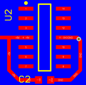
Below, is an example of what not to do. There is a copper plane on the bottom layer (the ground plane is not the problem) shown in blue and the top layer shown in red. The top layer has the footprint for an integrated circuit with a decoupling capacitor. Pin 4 requires +5V and pin 11 needs to be connected to ground. The copper traces between the capacitor and the power pins of the integrated circuit introduce a lot of inductance in series with the capacitor.
The next example is a much better design. The capacitor is placed very close to the power pin. The ground terminal of the capacitor is stapled directly to ground by two vias. The ground pin of the integrated circuit is connected similarly to ground.
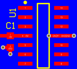
This design introduces much less series inductance.
Power Planes
One way to provide some additional, low-inductance capacitance is to have a dedicated copper plane both for ground and power. Naturally, the two planes form a parallel-plate capacitor whose capacitance can be approximated as:

Where ε is the permittivity of the PCB substrate, A is the total area of the two planes, and d is the distance between them.
Is series resistance always bad?
In fact, no! If you are designing an LC filter and the properties of your cap(s) are too ideal, you can create an ugly resonant peak at the corner frequency of your filter. Take the example below:
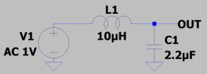
As you can see, there is a large, pesky resonant peak:
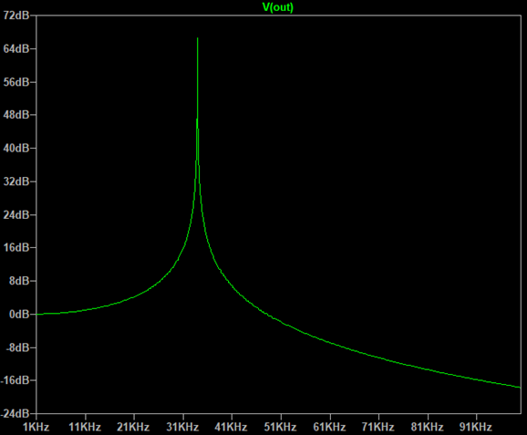
In this case, if the cap has a higher ESR, the resonant peak is reduced. Below, you can see the effect of giving the capacitor a 1.8 Ω ESR.[3]
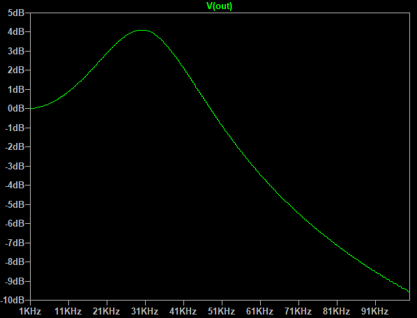
This peak can be substantially reduced by adding an RC damper (that is, a resistor in series with a capacitor) in parallel with C1. When values are chosen appropriately, this can dramatically reduce the resonant peak. This application note from Texas Instruments has more information on this subject: http://www.ti.com/lit/an/snva538/snva538.pdf
When designing with capacitors, issues can arise from their parasitic properties. The parasitic effects such as series and leakage inductance can be mitigated through good design, bandwidth can be increased, and some bad effects can even be turned into good.
Thanks for reading this article. I hope you’ve gained some useful insight and would enjoy hearing your tips and experiences.

[1] The graph was taken from this datasheet: https://www.knowlescapacitors.com/getattachment/6c8d48ef-fc2b-4752-ae2c-ce6c208de0c4/High-Capacitance-Chip.aspx
[2] For simplicity, series inductance is the only parasitic property included in this diagram.
[3]There are other parameters that are normally considered parasitic that can influence this. The equivalent series resistance of the inductor, etc.
Kris Dolberg is a StarFish Medical Electrical Engineer. He often writes on designing PCBs. Kris is a graduate of the University of Victoria where he was part of the ECOSat team that won first place in the Canadian Satellite Design Challenge.