How to get the most from your FDM 3D printer
Fused Deposition Modelling (FDM) desktop 3D printers have become a huge part of prototyping and testing. Knowing how to get the most out of your 3D printer is increasingly important when designing parts. There are countless factors that influence the quality of your final printed parts, such as print temperature, layer height, and print speed. Here are a few key things to keep in mind when designing parts for an FDM 3D printer.
Know Your Printer
It is important to get to know the printer you are working with. This could mean running your printer through a comprehensive battery of tests, or simply using fewer supports on parts and seeing what happens. You may be surprised by your printer’s capabilities.
- Depending on the material, most 3D printers can bridge gaps up to 50-100mm as long as they have a proper part cooling fan. There will be some drooping as the gap gets larger. This lets you use significantly less support material when printing overhangs that are supported on both sides.
- Many 3D printers can print very steep overhangs (60 degrees or more), especially at smaller layer heights. You won’t know if you don’t try!
- Similarly, most printers can print horizontal holes with a diameter of 30mm or more without the need for supports.
- While some printers may struggle with dimensional accuracy, the error between the target dimensions and the actual dimensions tends to remain fairly constant. If you can determine what this error is, you can account for it in your design and create more accurate parts. Keep in mind the error offset may change slightly depending on the material and settings you are using.
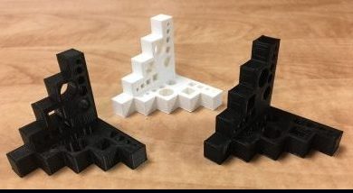
The image at the top of this blog shows three test prints used to test the dimensional accuracy of an FDM 3D printer.
Print Orientation Matters
How you orient a part on the build plate matters. You want to avoid creating geometry which will be weak, difficult to print successfully, or require difficult-to-remove support material. Correct orientation can mean the difference between a part that requires a large amount of support material, but still turns out poorly, and a part that needs no support material and prints great. It is important to keep this in mind when designing a component which will be 3D printed.
- FDM printed parts are non-isentropic: They are considerably weaker at the layer lines and will almost always fail along them. Therefore ideally you want to have forces run with the layer lines. Small vertical cross sections should be avoided if at all possible as they tend to break very easily.
- Consider which face will be touching the bed. You want to ensure there is plenty of surface area in contact with the bed so the part does not break free mid-print. Avoid steep overhangs that originate at the print bed as these tend to encourage warping.
- Consider your support material. While supports are often necessary, they are difficult to remove and result in poor surface finish where they are used. Consider where supports will be needed when designing parts, and work to minimize them. When supports are needed, ensure they are accessible and easy to remove.
- The resolution of your printer in the Z axis is dependent on your layer height, whereas the resolution in the X and Y axis is based on your nozzle diameter. Because your layer height will always be less than your nozzle diameter, you will be able to print thinner features horizontally.
Fillets are your Friend
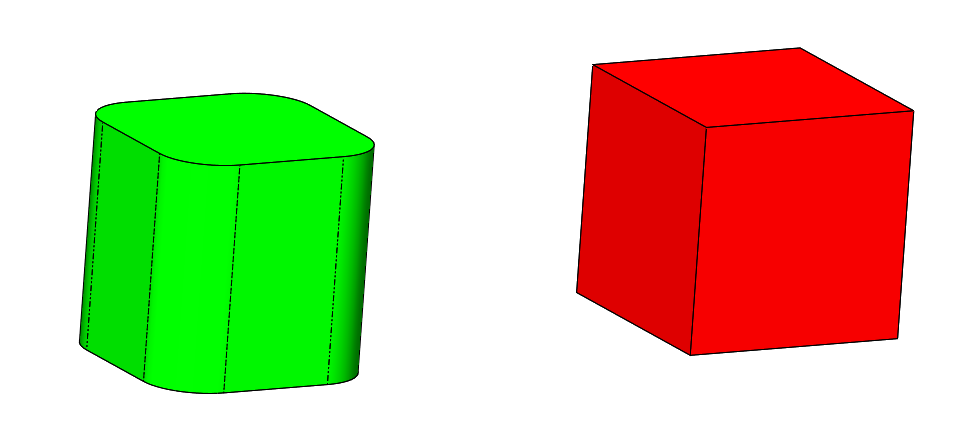
Even when designing simple jigs, it is worth it to add fillets to your parts. Unlike certain traditional manufacturing methods, there is no added time or expense to adding fillets to 3D printed parts. Adding fillets to printed parts results in parts that are stronger, print faster, and have a better cosmetic appearance.
- Adding fillets can slightly reduce the stress on the printer’s motion system, allowing it to print faster, and with less artifacts.
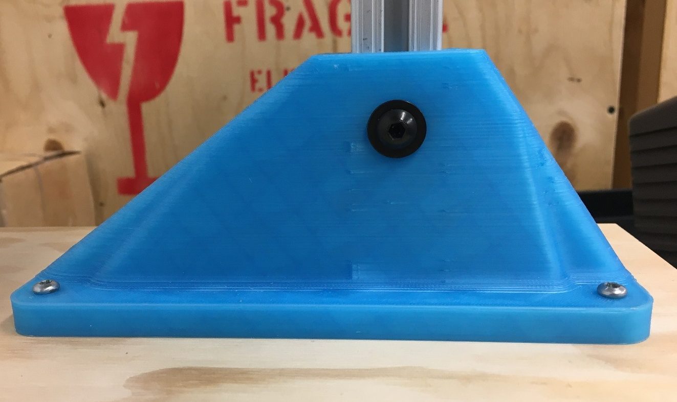
- FDM printed parts are non-isentropic and tend to break at their layer lines. Use fillets at the base of vertical features to help prevent them cracking or breaking at the corner due to the large stress concentration.
- Using fillets on sharp corners of faces in contact with the bed can help prevent warping. It reduces the localized cooling and shrinkage that happens in the corner by reducing the surface area.

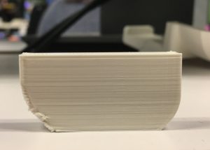
Side note: When designing a part, it is often desirable to add fillets to a face which will be touching the print bed. This can be problematic as the very steep overhang angle at the base of the fillet causes the print to warp up as it prints. At best, this results in a bad looking fillet because the layers are inconsistent and squished together. In the worst cases, this can result in the entire print becoming detached, or the extruder running into the warped part and skipping steps. Both situations will result in a failed print.
In order to fix this issue, use a 45 degree chamfer to start the fillet, then create the fillet off of that. The resulting fillet is never any steeper than 45 degrees and prints without warping or other artifacts. A chamfer half your fillet radius is usually close enough. If you would like to be precise, use a chamfer that is , or 0.5858 times your fillet radius. It will give you the exact same curvature as a fillet on its own.

Use Less Infill
I often hear people say they are using 60-100% infill to make their part strong. While this is sometimes correct, often such a high density is simply a waste of time and materials. When designing parts that will be experiencing little to moderate load, the walls of the part are usually strong enough on their own. In this case, infill is primarily used to give the walls something to build off of and provide a bit more rigidity. Jigs, fixtures, and even actual parts, are strong enough for most normal use cases with only 10-20% infill. However, I would usually not recommend infills below 10%.You can run into issues with top surfaces not printing correctly due to the lack of underlying structure.

Overall, keep in mind the unique capabilities of FDM 3D printing and how to get the most from your FDM 3D printer. The technology can allow features not possible with other manufacturing methods, but it can also cause problems if you do not address your printer’s limitations in your design. When designing parts for FDM 3D printing, it is important know your printer’s capabilities. Consider the part orientation you will be printing in as you design it. Add features like fillets to make your part print better. Be mindful of forces your part will endure. Chose an appropriate infill that will provide enough strength without wasting time and material.
Zach Mears wrote this blog while he was a StarFish Medical Mechanical Engineering Co-Op. Zach is from Victoria and studies Mechatronics Engineering at University of Waterloo, where he’s also a member of the rocketry club. Zach is a fan of paddling, focusing on outrigger canoe and ocean hiking, and enjoys spending time hiking and camping.
Images: StarFish Medical
