Tips for addressing DC bias effects in multi-layer ceramic chip capacitors
Last week my blog discussed a major drawback to multi-layer ceramic chip capacitors (MLCCs) that is poorly understood by even experienced engineers: DC bias effects on capacitance. So, now that we know that DC bias effects can be significant: what can we do about it?
I have adopted a simple procedure when placing a ceramic capacitor on a schematic. If I know the capacitor will be under DC bias greater than about 1/5th of the capacitor’s voltage rating, I ask myself a simple question: “am I okay with this capacitor having potentially 1/10th the rated capacitance?” If the answer is yes, there’s no problem. If the answer is no, it’s time to look at the manufacturer’s graphs and make sure the reduction in capacitance is acceptable.
Actually finding data for the expected DC bias effects can be difficult. Manufacturers often completely exclude this information from their datasheets, or if they do include it, there is only a vague mention like “capacitance loss guaranteed to not exceed 50% at 25% of rated voltage.”
If you want hard engineering data, you have to go beyond the datasheet. The major vendors offer this information in databases on their websites. Generally, you can specify an operating temperature and ripple figure and the website will output a graph of capacitance against bias voltage.
Here are links to engineering data for the major ceramic capacitor manufacturers:
- Kemet provides this data on their “K-Sim” site.
- TDK provides this data in their “Components Characteristic Viewer” database.
In addition to charts, TDK actually provides nonlinear SPICE models for the DC bias effect – currently the only vendor to do so. They are available here in HSpice, LTSpice, and PSpice formats complete with schematic symbols for easy schematic capture. This can be tremendously helpful when simulating an analog design, so kudos to TDK for going the extra mile to provide this kind of design support.
If you discover that a particular capacitor is unsuitable due to capacitance loss, you generally have three options:
- Use a larger value so that when the capacitance loss is taken into account, you still have enough capacitance for the job. This has diminishing returns: higher values tend to have even worse DC bias characteristics. This also doesn’t help in large-signal AC cases when you are worried about distortion, and likely will just make the problem worse.
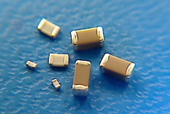
- Use a physically larger package size. As capacitor manufacturers have been driven to make smaller and smaller devices with more capacitance, they are forced to make compromises in their construction. This results in worse DC bias performance. So, if you can spare the room, moving from an 0603 up to an 0805 or a 1210 will significantly reduce your problem.
- Use a different capacitor type. Sometimes, you won’t be able to escape the DC bias issue. In this case, consider looking at a different capacitor type, such as an aluminum electrolytic or a tantalum.
Ceramic capacitors are extremely useful: they are a reason they are the most popular capacitor type in the world. However, understanding their drawbacks (such as the DC bias effect) gives you a useful tidbit in your design toolbox and will save you significant design headache down the road. I’ve shared my tips on DC bias effects. Now I’d love to hear others from readers.
Peter Kazakoff is a StarFish Medical Jr. Electrical Engineer. A recent graduate from the University of Victoria. Peter works on a variety of medical device projects that test his ability to manage the DC bias on capacitance.
Images: StarFish Medical
