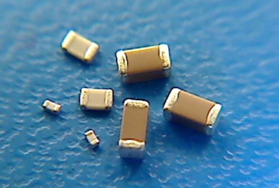
Understanding the effect of DC bias on MLCC capacitance
Multi-layer ceramic chip capacitor MLCC are the most common capacitor found in modern electronics. MLCCs have many attractive features: low ESR, good capacitance-to-volume ratio, relatively low leakage, non-polarity, and low cost. It’s no wonder that when choosing a capacitor, an electrical engineer will usually specify a ceramic first before any other type.
However, there is one major drawback to high-capacitance ceramic capacitors that is poorly understood by even experienced engineers: the effect of DC bias on capacitance.
A perfect capacitor is a mathematical fiction. Even a junior engineer fresh out of university knows that capacitors have series resistance (ESR), series inductance (ESL), and parallel resistance (leakage). This arrangement is often modeled with the following equivalent circuit:
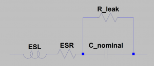
As the leakage of ceramic capacitors is relatively low, the leakage resistance is neglected in many applications and the capacitor considered only as a series RLC circuit.
This model, however, fails to capture the DC bias effect demonstrated by high-capacitance Class-2 ceramics. The materials used to build ceramic capacitors are ferroelectric, which means their polarization (and thus their permittivity) depends on applied electric field. As the permittivity of a capacitor’s material changes, so too does its capacitance.
This capacitance change can be shockingly pronounced. Consider a 4.7 uF, 25V, 10% X5R 0603 capacitor from Murata (P/N GRM188R61E475KE15). This size and value could conceivably be used as the output capacitor for a small switching converter. The following graph demonstrates the actual expected capacitance at 25 degrees Celsius with 0.01 V imposed ripple:
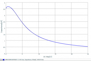
Under even moderate amounts of bias, the capacitance drops precipitously. At 10V (less than half the rated voltage), the effective capacitance of this “4.7uF” cap is only about 1.3uF. At the full-rated voltage of 25V, the capacitance barely exceeds 500 nF: almost a 90% reduction in capacitance from the nominal value.
Many engineers are aware of this effect but assume that provided they operate the capacitor under its rated voltage there is no concern, or erroneously assume that the DC bias variation is captured in the component tolerance of +/- 10%. As we can see with the Murata example, this is clearly not the case. Another common point of confusion is the temperature rating of ceramic capacitors: Class-2 ceramics are classified by a three-letter code indicating temperature range and change in capacitance over the rated range. For example, an X7R capacitor is rated to operate between -55 (X) to +125 (7) Celsius with a maximum capacitance variation of ± 15% (R). While this covers variation due to temperature change, it tells us absolutely nothing about the DC bias effects.
Another important point to consider is that the DC bias effect can exhibit hysteresis, as the ferroelectric material has a hysteretic P-E curve. This effect is usually less significant than the DC bias effect, but may be important in some large signal AC applications.
In addition to supply decoupling values being much less than expected, DC bias effects on capacitance can mess with your circuits in much more unusual – and infuriatingly difficult to troubleshoot – ways. An engineer might choose a large capacitor along with a large resistor to create a long RC time delay circuit. However, since the capacitance decreases with bias voltage, the RC time constant of the circuit will not be the resistance multiplied by the capacitance – instead, it will be some smaller value which will depend on integrating the DC bias-capacitance curve.
A less obvious issue might be using a large valued ceramic capacitor as a DC coupling capacitor in a large-signal audio circuit. Consider the following emitter-follower circuit used as a buffer amplifier for a small speaker:
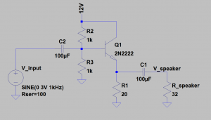
When the capacitors are modeled as ideal devices, the output from a SPICE simulation shows some minor harmonic distortion resulting from nonlinear behaviour of the transistor:
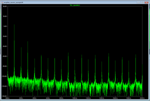
Now, we replace the ideal model with the SPICE model for a 100uF 1206 X5R ceramic capacitor from TDK:
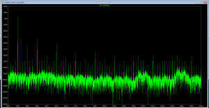
Despite the relatively small swing of +/- 3V, the output now contains significant new harmonic content which did not exist before, due to the nonlinear behaviour of the capacitor. If you had to troubleshoot this circuit to find the source of the harmonics, the series coupling capacitors are probably the last place you’re going to go looking – after all, a capacitor is a “passive” device and shouldn’t be introducing any nonlinearity, so your immediate suspicion is going to be the active device. You could potentially spend hours fretting over your transistor biasing without ever looking at the real culprit.
Peter Kazakoff is a former StarFish Medical Electrical Engineer. A graduate from the University of Victoria. Peter works on a variety of medical device projects that test his ability to manage the DC bias on capacitance.
Images: StarFish Medical
