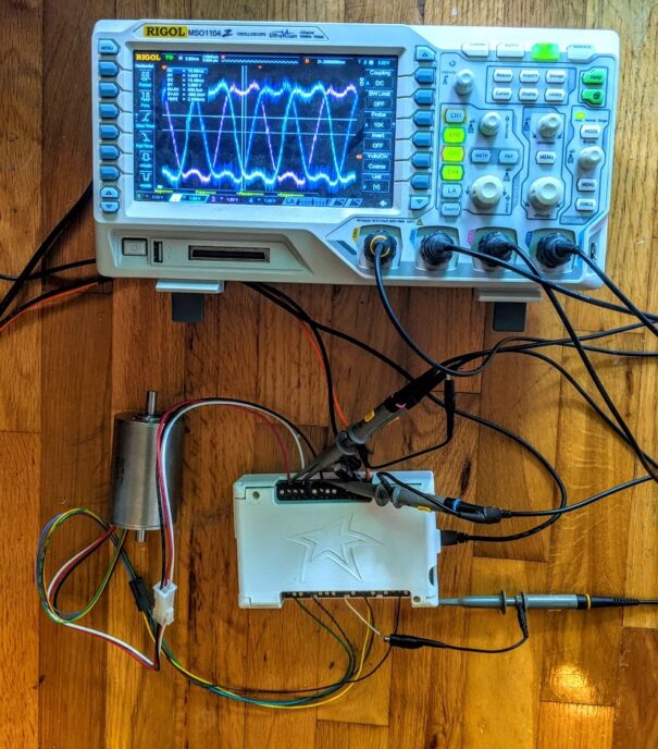
Designing BLDC motor drive electronics
Brushless, direct current (BLDC) motors are one of the options for motion control solutions in medical device development. A BLDC motor drive typically offers higher power, higher efficiency, and lower wear than comparably sized motors of other types. The main challenge in incorporating these motors is the complexity in the drive electronics and control strategy. As an example, we recently developed the Winnipeg Ventilator 2.0, which uses a BLDC motor drive at its core.
This blog discusses interesting considerations when designing BLDC motor drive electronics. I’ll cover some key details and concepts of these motors. In particular, I will focus on the particular strategy of driving the motor windings with sinusoidal waveforms.
Brushed DC Motors
Before getting into the detail of BLDC motors and drives, it’s a good idea to have a quick refresher on DC motors. A permanent magnet, brushed DC motor is one of the older electromagnetic machines.
Conceptually they are pretty simple, you can read my ancient blog where I built one with my kids. Essentially, they consist of one or more windings that rotate within two or more permanent magnet poles. Torque is generated through the Lorentz force and is proportional to the winding current and the magnetic field. In order to keep the torque direction consistent and maximized, the motor switches the current to the windings experiencing the highest field by means of conductive “brushes” connected to the motor terminals that sweep over a commutator that is connected to the rotor windings.
Brushless DC Motors
A BLDC motor operates similarly to a brushed motor but the magnets are on the rotor and the windings are stationary, and connected directly to the motor terminals. This is the most significant advantage of a BLDC motor: there are no brushes to wear out making them highly reliable over the lifetime of the medical device. Another advantage is that having the windings attached to the housing allows for more effective heat extraction compared to a brushed motor, especially at low speeds when convection is not as effective. On the other hand, the lack of built-in commutation means that the motor drive must provide this functionality instead, which in turn is probably the most significant disadvantage.
Winding and Motor Phase
Although there are often many internal physical windings, these are typically interconnected and wired to three motor terminals. For simplicity’s sake, I’ll consider the term “winding” as the difference between any two of the terminals and ignore exactly how they are implemented within the motor.
The three windings are driven in a typical three-phase relationship where each winding is 120° offset in phase from the other two. When the first winding is at zero degrees of its phase cycle then the next winding will be 120° ahead and the other will be 240° ahead (or 120° behind). Note that winding phase angle does not directly correspond to rotor angle. There are typically quite a few phase rotations per full rotation. This is essentially equal to the number of magnetic pole pairs in the motor.
As with a brushed motor, the windings must be energized in just the right way depending on the phase angle. Because BLDC motors don’t have a commutator attached to the motor shaft, information about instantaneous angle must be conveyed to the drive. This is typically achieved via signals from three Hall sensors. Each signal indicates the direction of the magnetic field of each winding. The transitions of these signals represent key waypoints through a 360° commutation cycle.
Note that there are other strategies of determining the winding phase angle, such as inferring from the EMF of the windings or using optical encoders but we won’t go down those rabbit holes in this blog.
Driver Output Topology
During a full commutation cycle, the motor drive must alternate between full current into a particular terminal to full current out of that terminal. To achieve this, the typical topology consists of one half-bridge output per terminal.
Although it is often omitted, I prefer to implement each half-bridge with an LC filter at its output, so each one looks essentially like a buck converter. This allows all of the high frequency PWM switching to be confined within the PCB. This is especially helpful if the motor is not particularly close to the drive.
With an LC filter, you have to pay attention to the filter resonance: this must be above your highest drive frequency but significantly lower than your PWM frequency. On the plus side, you’re not relying on the motor inductance to cope with the rapidly switching voltage. That saves worrying about motor core losses and saturation.
Why Sinusoids for BLDC motor drives?
Most BLDC motors are designed such that the net magnetic field experienced by each winding varies sinusoidally with motor rotation, or as near as possible. You may remember that a three-phase sinusoidal system has uniform power transfer. In the case of a BLDC motor, this means uniform torque. If the field varies as a sinusoid, then the EMF will as well. If the drive voltages are also sinusoids, then the currents will be too.
Sinusoidal drive also minimizes the higher harmonics which is good for minimizing RF emissions.
Computing Motor Phase
The next step in our journey is the computation of winding phase from the Hall sensor signals. As I mentioned earlier, these signals indicate the sign of the magnetic field of the three windings. Their instantaneous values can be used to coarsely estimate the motor phase. This is useful at very low speeds when the rotor velocity is not well known.
Once the motor begins turning, the transitions of the hall sensors give very precise way points of motor phase and can be used through a dead reckoning process to estimate the instantaneous phase very accurately. At reasonable speeds the rotor velocity does not change substantially from sensor transition to transition so extrapolating from the last few transitions is quite practical.
There is one final nuance to the phase calculation. As the motor velocity increases, its phase and particularly its current will be increasingly affected by the motor winding inductance and resistance as well as by the LC filter. The EMF generated by the magnets interacting with the windings also sees a phase shift. This has the effect of limiting the top speed that can be achieved: the phase delay eventually grows large enough to cause the torque drop off to the point where it cannot accelerate further. The work around for this limit is to phase-advance the drive waveform. Similarly, at speed, the phase may need to be delayed when a reverse torque is desired. This phase correction can be proportional to motor speed but it works pretty well simply to apply a constant shift depending on the desired torque direction.
Generating Waveforms
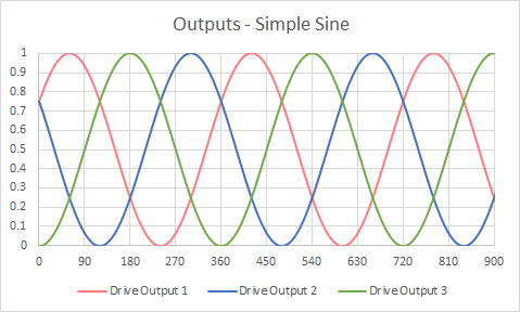
Now that we know the desired phase, we can compute the output waveforms. The simple approach is to compute three 120° phase shifted sine waves, one for each half-bridge output. It turns out that this is not quite optimal.
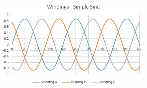
Since the winding drive voltage is actually the difference between half-bridge outputs and the outputs are 120° separated, then the windings will never experience the full rail voltage. The difference between windings will be 13.4% lower than the rail. The following graphs show normalized output voltages and winding voltages. Note that the winding voltages don’t reach all the way to one.
We can fix this by subtracting the lowest instantaneous half-bridge output from all output waveforms. That allows us to scale our drive up and achieve a winding voltage up to our supply rail. The winding voltages remain sinusoidal, but the half-bridge outputs are not. I’ll call this a “maxed” waveform. You can see in these graphs that the windings to reach one but the output voltages have some pretty sharp edges.
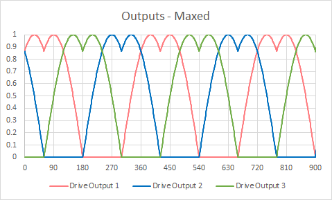
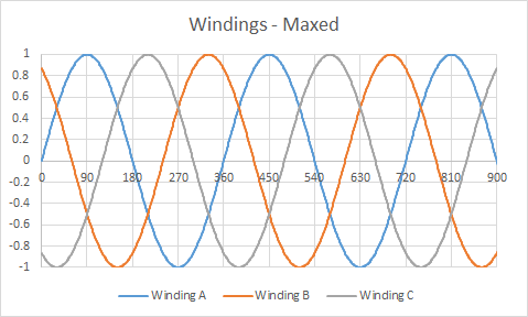
This subtraction trick is great for achieving the highest motor speed for a given power supply voltage, but the sharper transitions in the half-bridge outputs cause higher harmonics in the motor wiring which again can cause EMC issues.
A further improvement to the drive waveforms is to approximate the above lowest output subtraction by instead subtracting an appropriately sized third harmonic of the drive frequency. This approximates the perfect subtraction with a pure sine wave, thereby limiting higher harmonics to only the third. I’ll call this the “smooth max”. In these graphs we get both full-range winding voltages but also pretty soft looking output voltages.
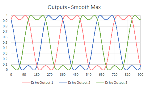
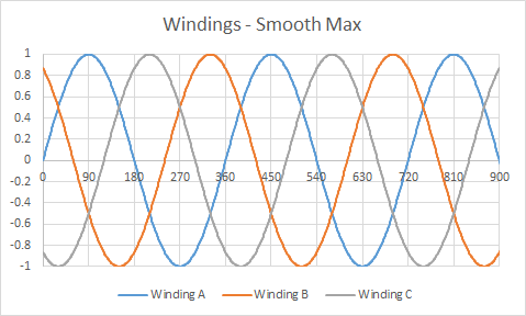
Whichever waveform you choose, you have the choice of either computing the instantaneous waveform values using trigonometric functions or precompute a lookup table and interpolate within it.
In this blog I’ve described enough BLDC background in order to get to a few of my nuggets on sinusoidal drive strategies. Tricks like these enable us to successfully use these more sophisticated motors in our medical device designs.
Images: StarFish Medical
Kenneth MacCallum, PEng, is a Principal Engineering Physicist at StarFish Medical. He works on Medical Device Development for a variety of areas including ultrasound applications. Kenneth would enjoy hearing from readers about their reference designs and experiences.
