Prototyping electronic systems: Tips for avoiding rework
When prototyping electronic systems or creating a first proof of concept prototype, it’s tempting to jump right into the lab and start soldering bits together.
In my experience, creating developmental test boards early has always paid off. I’ve learned that a proof-of-concept (POC) mess-of-wires, even with the best of intention and care, is almost never reusable and can lead to hours in the lab troubleshooting problems that could have been avoided. Project permitting, a few more days and some extra material cost at the beginning of a project spent on prototyping electronic systems can save weeks during subsequent efforts.
As Electrical Engineers (EEs), we’ve all had this conversation:
Project Manager: Hey Keen EE! How long would it take to connect up all of these off the shelf devices with some extra components mounted to some proto board? We’d like to show off a bench-top proof of concept ASAP.
Keen EE: Well, I’ll have to hack up a bunch of standard cables, order crimps and connector housings to make new cables, order ICs, IC breakout boards, pin headers, and liberally use hot glue to ensure that once connected, nothing moves. It won’t be pretty.
Project Manager: (blankly stares and gives that “You’re not giving me what I want to hear” look.)
Keen EE: A few days… no problem. We’ve run into reliability problems in the past, but THIS time… no problem.

The next logical questions for both of our players is ‘Are any of these components expected to be used in the final embodiment? Or is this actually and truly a short term, one-off demo system that will be recycled after the demo?’ If there’s a chance any portion of the POC will be reused, it might be time to get creative with the use of PCBs to reduce interconnections, provide proper component footprints, test points, and extra pads for components that may or may not be needed. We EEs can dig through PCB design libraries to quickly place and connect parts without needing a lot of hand-wiring, and the resulting PCB design files serve also as documentation of the evolving POC.
If there is particular functional or Electromagnetic compatibility (EMC) risky component, an early PCB iteration may be used as a test bed to mitigate it. Furthermore, if additional features need to be added and tested in your system before your next design spin, a test board can make it much easier to ‘barnacle’ on new components securely so your firmware team member may get a head start writing code for the new functionality.
The POC system may include off-the-shelf finished products (a common consumer, medical, or industrial device) to reduce time spent designing something that is already available. Products such as industrial automation controllers typically have standardized connectors and terminals and can be quickly swapped as the design evolves. Increasingly, manufacturers provide 3D models of their components, which makes it easy to incorporate them using modern PCB design software.
To use one of these off the shelf products, simply design a break out board that mates with its connectors and brings all signals out to a single low profile cable or a board edge connector to mate with your custom PCB that forms the rest of the POC. This board pops onto the side of your off the shelf device and significantly cleans up your experiment. You will also reduce cable/connector bulk: your mechanical and industrial design team members will applaud your efforts and Kenneth will undoubtedly approve.
Leveraging existing microcontroller development boards like the STM32DISCOVERY line is great as there is already a powerful embedded processor, programmer, regulator, and all kinds of other goodies mounted to it, not to mention a reference schematic and the fact that they’re awesomely cheap. In order to break the signals out to your custom system components, you just have to provide strategically placed female headers on your POC PCB for the microcontroller board to just pop right on.
In the end, both methods will provide a functional POC demo, but a PCB-based development platform will have the flexibility to accompany your design through the next steps. . The big question is: would you rather be spending time soldering together a bench top experiment, or a very early iteration of your future (successful) product?
Christian Proch-McMechan is StarFish Medical Principal Electronics Engineer.
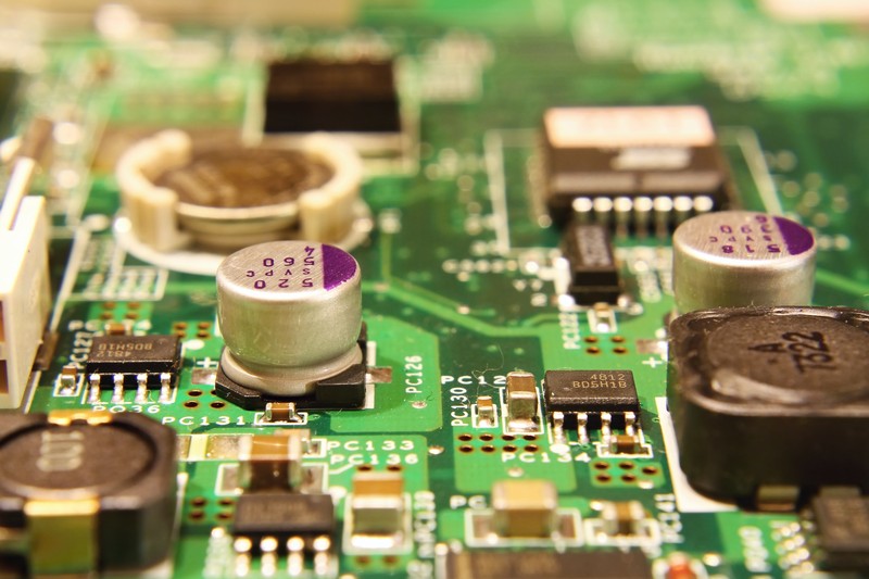
Image: 19972420 © Yommy / CanStockPhoto.com
