10 Tips for Ultra Low Power Embedded Design
The demand for medical devices that must do more with less power is continually increasing. So, what kind of tricks can we designers resort to in order to keep up with increasingly stringent power requirements? As usual, creativity and good judgement play a key role in successful designs.
Here are 10 tips to help improve the power efficiency of your ultra low power embedded designs.
Tip #1 – Take advantage of switching supplies efficiency
One of the easiest places to make an efficiency impact is in the power conversion stages. Switching controllers are increasingly simpler to integrate. They often require only a few additional passive components when compared to their linear counterparts. Some modules, like the TI TPS82740, even integrate the inductor and filter capacitors. High frequency and synchronous operation result in smaller components and higher efficiency while burst mode operation offers a respectable performance at very low currents. Reference designs and free simulation software (Ex. LTSPICE) make integration almost effortless.
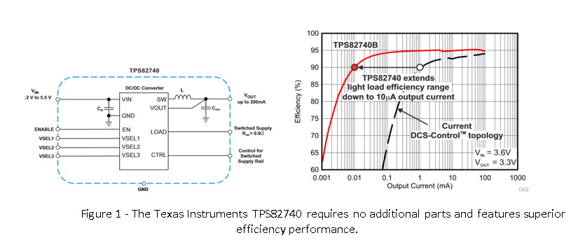
Note that systems with extremely low duty cycle may be impacted by the switcher unloaded quiescent current.
Tip #2 – Partial power-down
Where the quiescent power requirements are very stringent, consider removing power altogether from peripherals when not in use. This can be achieved in several ways:
- Use a MOSFET switch: Ex. a low-side switch (NMOS) connecting the peripheral ground to the system ground or a high-side switch connected to the peripheral supply. Then, control the MOSFET gate from an MCU output.
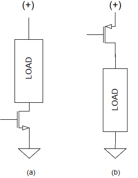
FET switches are not perfect and a typical small signal FETs leakage is in the sub-microamp range. Nonetheless, specialty parts exist that drop this current down to the tens of nanoamps (ex. Texas Instruments FemtoFETs).
- Use a dedicated ultra-low leakage load switch like the one shown in the figure below:
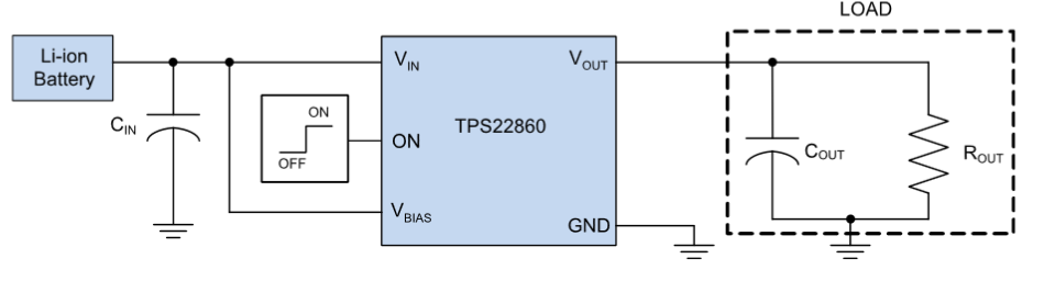
- Use a general purpose output from your microcontroller unit. It is not uncommon to find low output impedance MCU GPIOs that are able to source tens of milliamp. To selectively power a subsystem without using additional parts, use a general purpose output as a ‘switchable’ supply. One word of warning: consider that power will likely be contaminated with digital noise. This technique is not recommended for powering noise sensitive analog components unless some filtering is put in place.
Tip #3 – Beware of spurious phantom powering and latch-up
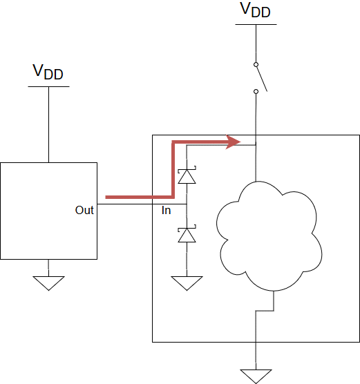
Selectively unpowering parts of a system is a valid approach to save power. Care must be exercised. The designer must beware a phenomenon known as spurious phantom powering. Spurious phantom powering occurs when currents find their way to the power supply pins of a deactivated part through alternative paths. A very common way to inadvertently power a device is through its inputs via the ESD protection diodes as shown in Figure 3.
To prevent this from happening, use a buffer with power-down isolation (ex. SN74LVC3G34 ) in the signals flowing into the powered down part as shown in Figure 4.
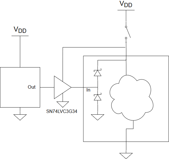
Power down isolation guarantees that input and output of the buffers will be isolated when power is removed from the buffer, effectively blocking any current into the input of a powered down device.
Another phenomenon to take into account is CMOS ‘latch-up’. A latch-up condition occurs when a low impedance path between the supply rails of a part is formed by triggering a parasitic SCR (Silicon Controlled Rectifier, Thyristor) in the I/O stage of a CMOS chip. That low impedance path can lead to the destruction of the part if enough power is made available at the supply rails.
A latch-up can be triggered by applying a voltage to an input or output pin that exceeds the supply by more than a diode drop. It is easy to see how this could occur if a digital signal was supplied to a powered-down part. Using a buffer with power-down isolation will also protect against latch-up by blocking the current into the powered-down part.
Tip #4 – Reduce the supply voltage of power hungry peripherals
A general rule for switching (clocked) digital parts is that their power consumption is proportional to the square of their supply voltage. This is because most of the energy expenditure goes into charging (and later discharging) internal capacitances (E=1/2 C V^2). Another valid and fairly cheap way to reduce power is to operate parts in the lower end of their supply specification.
Additional circuitry may be required to adapt the logic levels of parts operating at different supply voltages that need to interact with each other. Fortunately, a variety of single chip logic level translators make this task straightforward.
Tip #5 – Consider the impact of pull resistors
Pull resistors can hurt the power performance of a design when they are arbitrarily chosen to be low. In general, if not always, current flowing through pull resistors is wasted. The choice of pull resistors is usually a trade-off between power efficiency and high speed signal integrity. Choose the highest value you can get away with that will not hurt your high speed performance, but with a strong enough “pull” to fulfill its purpose.
Pull-up resistors sometimes offer supply leakage paths that will impact your design quiescent performance. It is worth looking into converting them to pull-downs when possible and convenient.
Tip #6 – Do not allow digital inputs to float
Unused inputs must always be tied to ground or pulled up. Floating inputs may cause internal circuitry to toggle (this is particularly true for non-Schmitt trigger inputs) or wander at intermediate potentials that can significantly increase the supply leakage. In my experience, a floating MCU input can increase the quiescent consumption by several microamps.
If an output driving an MCU input is tri-stated when in a sleep state, consider temporarily configuring the input as a low-driven output. This strategy usually yields better results than using a pull-up resistor.
Tip #7 – Tune your core clock to the lowest speed you can get away with
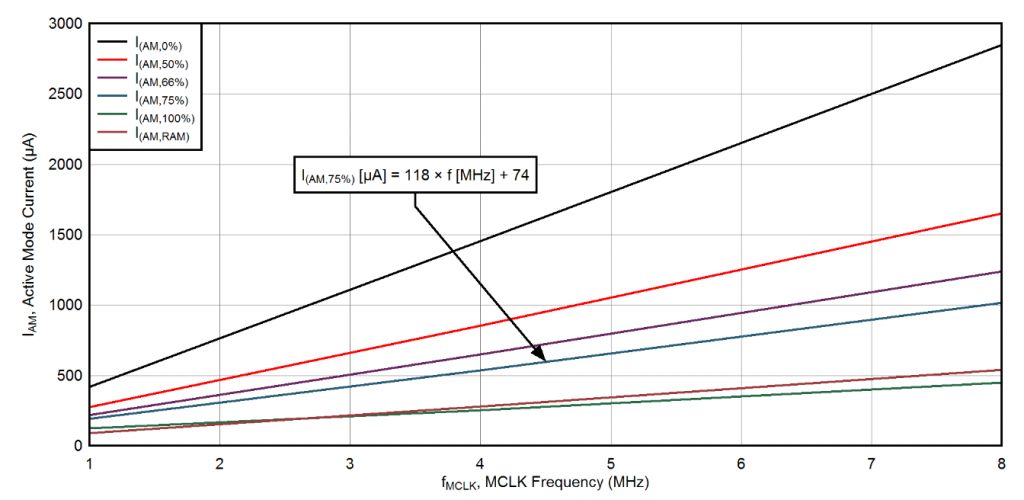
This one is another ‘no brainer’. Power consumption will scale almost linearly with the core frequency (see Figure 5). If a section of your code needs to run faster, you can always throttle the clock temporarily.
Tip #8 – Take advantage of MCU low power modes
Most microcontrollers offer a variety of low power modes that the designer can activate at different times during the execution of the application. These power modes selectively disable peripherals thus helping reduce power consumption.
Tip #9 – Put your MCU to sleep instead of idling
Avoid idling loops waiting for an external peripheral event. Instead, set up a wake up event and put your MCU to sleep. If your design makes use of a real-time kernel, consider putting your MCU to sleep in between ticks while in the idle task. Note that there will be a trade-off between the energy spent recovering from a sleep state and the tick frequency.
Tip #10 – Consider using a kernel with tickless operation capabilities
At the core of common real-time kernels a periodic interrupt (tick) is used to process a scheduler that switches the execution context to different tasks according to their priority and readiness status. If using Tip #9 to save power, the adjustment of the tick frequency becomes a tradeoff between power savings and responsiveness to events. In other words, increasing the tick frequency makes the system more responsive by decreasing its latency, but at the same time it increases the power losses due to the energy spent waking up the core more frequently.
When operating in tickless mode the kernel suspends the tick until an interrupt occurs or until it is time to transition a task into the ‘ready’ state. In this way the system is spared from needlessly waking up and have the scheduler find out that the idle task must continue to execute (i.e. it has to go back to sleep immediately).

Diego Sorrentino is Electrical Engineering Team Lead at StarFish Medical. He received his BEng (Hons) Electrical Engineering from the Buenos Aires Institute of Technology, and his M.A.Sc Electrical Engineering from UVic. When not reducing medical device energy consumption, he sails and plans to get a pilot’s license.
Title Image: 15254509 viperagp / Can Stock Photo
Other images used with permission from Texas Instruments Incorporated.