3D-Printing Prototype Sheet Metal Parts
Prototype Sheet Metal Parts in 4 steps
Sheet metal fabrication is an excellent method of making mechanical parts, especially support brackets. They tend to be cheap, light, strong, and easy to pack and ship. However, a major drawback to sheet metal is the setup costs in prototyping: a part might only cost $10 to make but cost $500 to set up.
Down the road, that cost is absorbed in high volumes –500 parts would only cost $11 each – but if you’re ordering just a couple to build a prototype, you’ll be paying $260 each for one pair of small brackets. Ouch.
This blog shows a step-by-step method to save cost by using 3D printing to prototype a cable support bracket. The most suitable printing methods are those that trade-off resolution for strength and cost, and are more isotropic, such as SLS or MJF (interestingly, metal 3D printing is also possible, but not usually worth the cost).
In the example below, the final cost was quoted as $504 total for 3 units in sheet metal with a long, multi-week lead-time, or over $1000 for a faster two-week lead-time, but only $150 total in SLS Nylon for 5 days lead-time from an online rapid 3D prototyping vendor. Nylon parts don’t perform as well as sheet metal in high-strength situations, but are strong, flexible, and inert enough for many prototyping applications.
Parts must be tweaked in CAD by creating a single solid body. The exercise shown below took about 20 minutes.
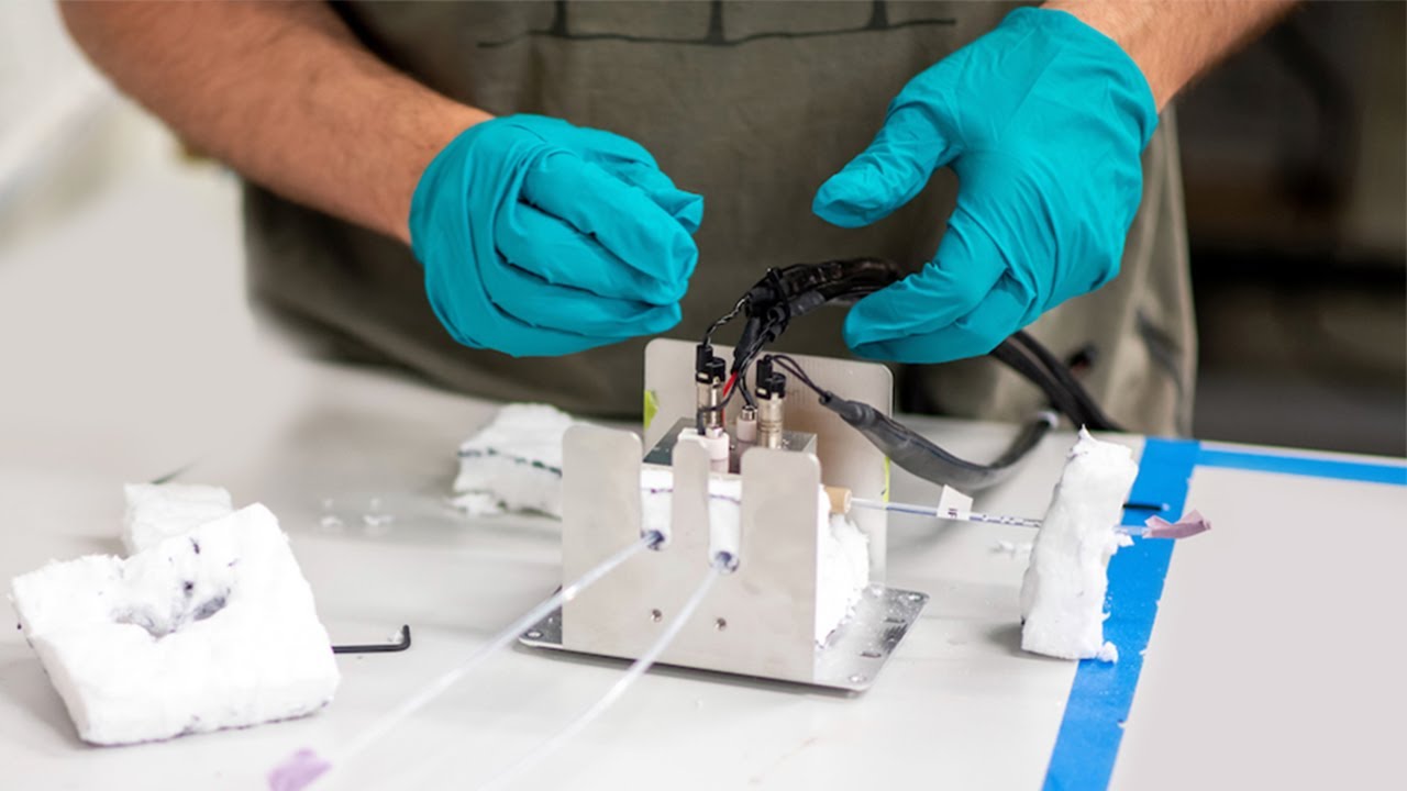
Suitable parts will have complex 3D shapes or welds, be relatively small, and be required in small quantities. They will not require the full strength or heat resistance of metal or the specific aesthetic of the final metal part and will be used for short term prototyping only.
An important drawback to remember is that tolerances are usually better in 3D printing than in sheet metal, so the prototype part may not be entirely representative of the final part (i.e., the 3D printed part may fit nicely where the sheet metal part does not – an unwelcome surprise in later stages). This can be mitigated through good sheet metal design practices, such as using slots instead of holes where appropriate.
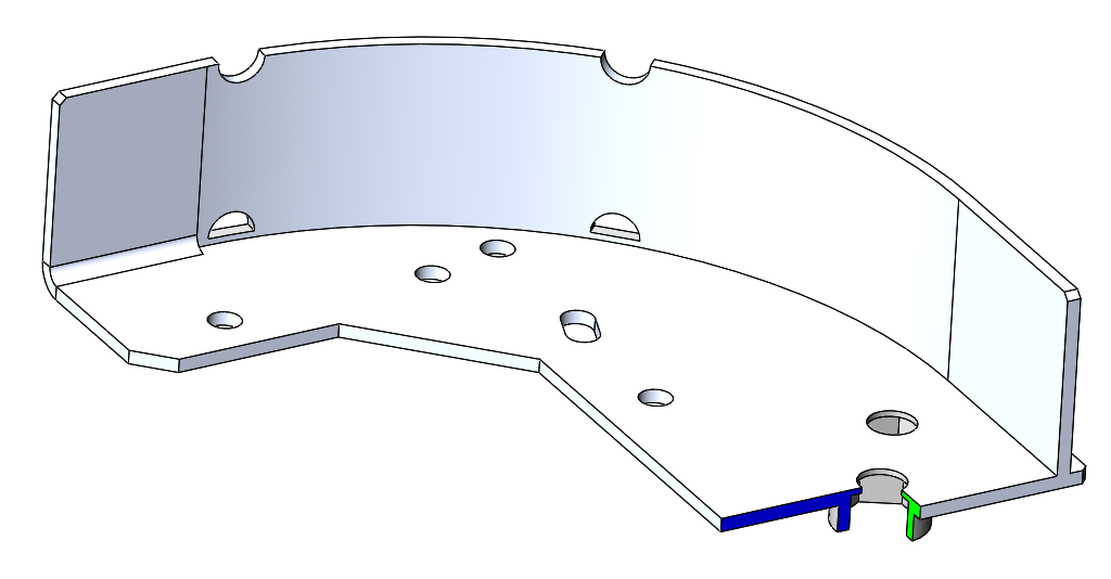
Example: cable support guide bracket
Step 1: Save your finished sheet metal assembly as a part by selecting ‘all component geometry’ (this will save it as a solid). If you aren’t making an assembly with inserts, you should still save your sheet metal part as a new file to ensure your original part is unchanged.

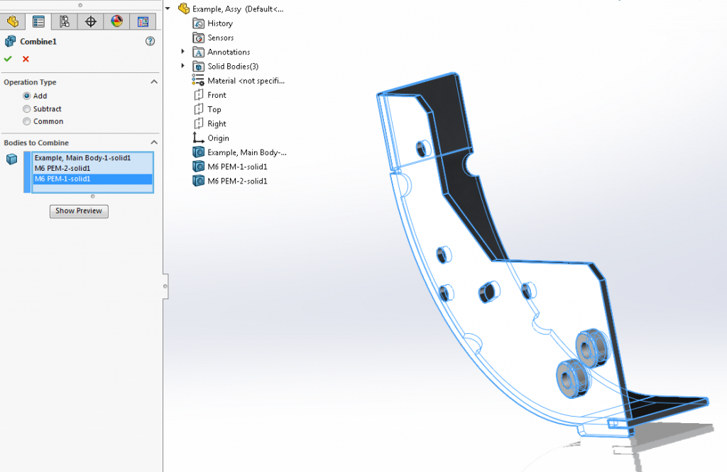
Step 2: Use the “combine” function to combine all solid bodies into one solid body. (Again, only necessary if you started with an assembly)
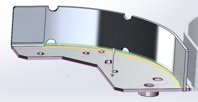
Step 3 (optional): Fill gaps and make printing easier
This step may not be necessary, but you’ll end up with much stronger, easier to print parts if you fill in any gaps between nearby bends. It is usually quite simple to do by just using the “covert entity” function and extruding the resulting sketch.

Step 4 (optional): Strengthen and replace inserts (you can alternatively just eliminate the inserts and use a floating nut if that’s suitable)
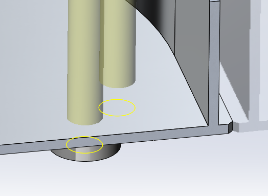
Depending on how you’ve modelled your parts and which program you’ve used, there is a good chance your inserts won’t actually be connected as solidly as possible in the model. Even worse, they likely will likely have a pre-tap hole size rather than a clearance hole. In this example, the M6 self-clinching insert has a small gap between the sheet metal and only has a 5mm hole in the CAD model. Other inserts (for cable ties, etc) also have this issue. This step fills those gaps (literally) to ensure strong parts.
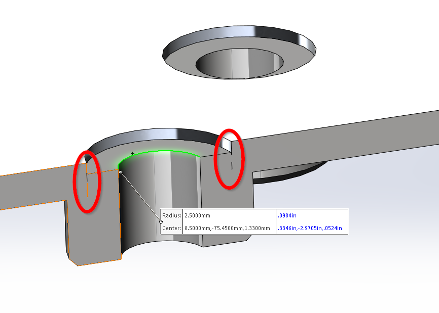
4.1 Extrude a solid core right through the insert to fix the gap issues. I also added some diameter as we’re going to need it later.
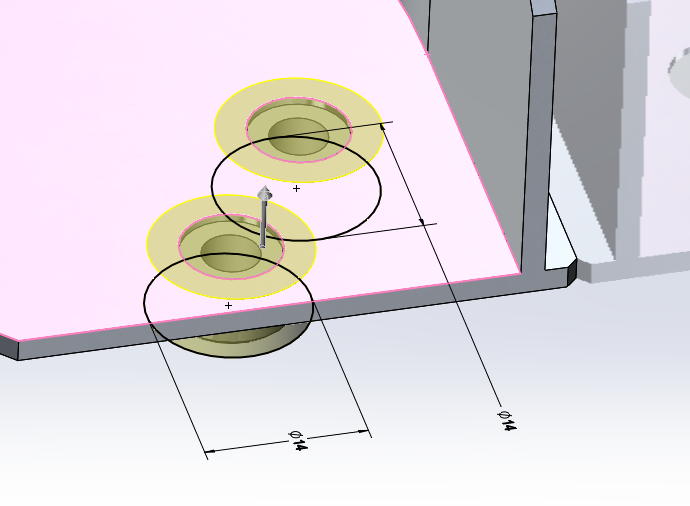
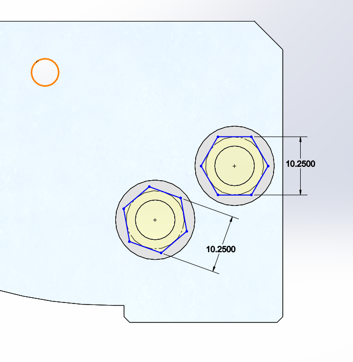
4.2 Then add your clearance holes using the hole wizard tool.
4.3 Instead of the threaded inserts, we’re going to use some crazy glue to stick in off the shelf hex nuts (you could also use an interference fit and press the nuts in without glue, or use heat set inserts). This method is very simple and fast to implement, and provides a nice strong thread. This is why we added the extra diameter earlier – M6 hex nuts are too large for the standard insert outer diameter.
And that’s all there is to 3D-Printing prototype sheet metal parts. Now you can print your parts for less and receive them faster than you might using traditional sheet metal methodology. Happy prototyping!
Nigel Syrotuck is a StarFish Medical Mechanical Engineer and frequent guest blogger for medical device media including MD+DI, Medical Product Outsourcing, and Medtech Intelligence. He works on projects big and small and blogs on everything in-between. He is currently working on 3-D printing a prototype of his work “stand-in” for upcoming vacation time.
Images: StarFish Medical