Choosing and integrating a medical device stepper motor
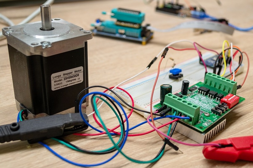
Recently almost every medical device I design requires a stepper motor. After working with these motors so frequently, I’d like to share what I’ve learned about medical device stepper motors, the different types of stepper motor configurations, and how to drive stepper motors properly.
What is a Stepper Motor?
A stepper motor is a brushless DC electric motor that moves a specific number of physical degrees per electrical step. This is defined as the step angle in most data sheets. It defines the rotational resolution for a particular model of motor. A convenient property of stepper motors compared to traditional motors is their ability to move at a variable speed in either direction, then come to a full stop and hold a position with reasonably high torque for an indefinite amount of time (heat generation permitting). This is defined as holding torque, which is the amount of torque needed in order to move the motor one step when the windings are energized at the rated current and the rotor is stationary. A stepper motor can use open loop motion control. This means a controller keeps track of the number of steps it has taken and knows the position in degrees that the motor has turned. Open loop motion control is useful for linear motion applications that drive a lead screw or belt, such as CNC machines, 3D printers, or syringe actuators.
Stepper Motor Drive Configurations
Stepper motors typically come in two motor winding configurations. Before selecting which configuration is appropriate for your application, you should understand the basic difference between the two. This choice will be important when selecting how to drive the motor.
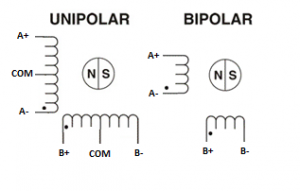
The first configuration type is a unipolar motor. Unipolar stepper motors have a winding with a center tap per phase (see Figure 1) which makes them particularly easy to control. The center tap of each winding can be common to both phases. The outer two ends for each winding can be controlled with a single transistor. For the simplest unipolar driver, only four transistors are required for bi-directional motion. The easiest way to identify a unipolar motor is they typically have five or six leads depending on whether the center tap has been internally connected or not. A downside is that half of each phase is de-energized during each step. This means that unipolar motors are typically larger and weigh more compared to a bipolar motor.

The most popular configuration is a bipolar motor. Bipolar stepper motors have a single winding per phase (see Figure 1). The current in a winding needs to be reversed in order to reverse the direction of motion. In order to achieve bi-directional motion, a full H bridge per phase is required in order to drive a bipolar motor. The real benefit to using a bipolar stepper motor is their improved efficiency compared to the unipolar motor. The entire winding is energized during motion which translates into smaller and lighter motors that can produce a surprising amount of torque. The easiest way to identify a bipolar stepper motor is that it will have four leads, two per phase and none are common.
Pro Tip: You can use a unipolar motor as a bipolar motor if you ignore the center tap. This can come in handy if a particular design of motor is only available in a unipolar configuration.
Stepper Motor Drive Signals
Typically three types of drive signals are used to control the motion of a stepper motor. Each drive type increases in complexity, but adds additional features and options.
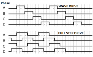
A wave drive only energizes one phase at a time. Wave drives are simple to implement with basic hardware, but are rarely used. Because only one coil is energized at a time, torque is significantly reduced.
A full step drive is similar to the wave drive but both phases are always on. This results in maximum rated torque applied to the motor. The timing sequence in a full step drive also promotes smoother rotation as the next phase is not abruptly energized, but instead smoothly introduced during rotation.

The micro-stepping/sine wave is typically implemented by integrated stepper motor drivers to produce a coil current that approximates a sine wave. Popular for systems that require smooth operation, the sine wave reduces motor noise (Fourier Transform). It typically requires additional circuitry as the integrated circuit (IC) usually monitors and controls the current with a feedback control loop.
Stepper Motor Drive Circuits
The most common methods for driving a stepper motor include a simple constant voltage or L/R (L refers to electrical inductance and R stands for electrical resistance) driver, a chopper drive, or a sine wave/micro-stepper driver.
The L/R driver circuit uses a constant voltage to drive each coil. In an L/R circuit the coil’s time constant limits the maximum amount of current that can be supplied to the coil governed by the relationship between the coil’s inductance and resistance. To maximize motor torque, current must also be maximized. To achieve this in an L/R circuit, typically a large drive voltage is used to offset the inductance. This drive method is less popular nowadays as we can produce higher torque with less heat generation using modern switching techniques.
The second and more common drive method is an integrated chopper. A chopper attempts to overcome the coils inductance by applying a high voltage over the coil and chopping it after the current has reached a set threshold. Using a sense resistor and a feedback loop, the input voltage is chopped in order to achieve the desired current in each coil. The major benefit of this drive design is the ability to shorten the current rise time by overcoming the inductance, but not overly burning energy once the step has completed. The drawbacks to using a chopper are that it requires additional electronics to sense current, requires a high voltage source, and requires switching control. However, this can all be taken care of by using a stepper motor drive integrated circuit.
Stepper Motor Integrated Drivers
Once a stepper motor has been selected to suit its mechanical requirements, the next thing is to get that motor turning. It is easier than ever to make a motor operational by selecting an off the shelf stepper motor driver IC or development board. Many of these boards provide features such as current feedback, built in acceleration profiles, and even onboard path planning for more complicated motion control.
Some of my favourite controllers that can be easily incorporated into almost any device include TI’s DRV8825, or DRV8834 Stepper Motor Controller, or any of Trinamic’s stepper motor driver ICs. In particular, Trinamic’s ICs can manage everything for you and provide a nice silent mode of operation, stall prevention, and path planning.
Almost all stepper motor driver ICs have the option to be ordered as a development board with simple power connections, motor connection, and a configuration through solderable jumpers, removable jumpers, or a UART connection. Once the concept is proven to work appropriately, the actual stepper motor driver IC can be easily incorporated into a custom PCB following the manufacturer’s recommended layout and design considerations.
I hope you found this information helpful and have a better understanding of medical device stepper motors and how to drive them.
Martin Kellinghusen, is a Electrical Engineer Team Manager at StarFish Medical. A graduate of the University of Victoria, Martin has worked on a variety of medical devices and is passionate about electrical engineering – specifically anything that drives, flies, or goes fast!
Free photo 135689614 © Publicdomainphotos – Dreamstime.com