Six tips for medical device CFD simulations
Knowing when to use simulation versus when to physically build a device depends on the problem and what you are trying to do.
Computational Fluid Dynamics (CFD) is a powerful tool for predicting and optimizing fluid and thermal paths. Medical device CFD simulations offer the added benefit of being able to generate images and videos with very little effort. For the non-technical stakeholders in a board meeting, images and videos can be a compelling tool to demonstrate technical competence. But how do you know if the simulation is actually representative of reality – or even useful?
Here’s a rule of thumb based upon some recent projects including electronics heat dissipation with a forced air fan, patient contacting conductive cooling, maximizing air exchanges in a constrained environment, and predicting pressure drops of a porous media, amongst others. Where gross approximations are appropriate, or data is available (such as sizing a pipe with a Moody Chart) this is best done with first principles calculations. More complex situations with simple parts are really best addressed using build and test.
Assuming CFD is appropriate, here are some quick and simple things to look for in assessing a fluidics problem:
Physical Data / Testing
Unless the CFD is very well contained and predictable, physical testing of mockups using off the shelf components or rapid prototyped geometries can provide confidence in simulation work. Unusual or unpredictable geometries are prime candidates for building and subsequently iterating into CFD models. Optimization is the bread and butter for CFD, but refining the model to ensure it represents reality is often better done with a quick and simple physical test.
Localized Mesh
Many problems within the CFD world have areas of interest where computation power should be focused. In the simplistic case of an electronics box with an inlet fan, outlet, and a component right in the middle of that box that is giving off heat, don’t invest too much power calculating the temperature in the corner of the box. By locally refining the mesh, higher accuracy of results can be achieved in less time. A meshed model will provide insight into the element sizes and level of refinement that went into the model. As a rule of thumb, having small gaps of interest be represented by three complete fluid cells across its cross section will often provide reasonable results.
Convergence
Perhaps more difficult to assess from a slide deck, understanding if the model is converging to reasonable goals is important. This is particularly true for applications where precise temperature resolution is required and the convergence goals are set within a band that is unacceptable for the end application. For instance, if the application is for measuring body temperature, having a convergence goal of +/- 1deg C does not seem like a suitable target, as the final specification for the device accuracy is likely to be more granular than this. The surface on which a convergence is set is equally as important.
Simplified Geometry
Don’t be afraid if your model does not look like the overall assemblies. Where CFD models are required to be run in an assembly, simplifying the analysis by capturing the fluid path as a single feature can save time and yield better results. The fluid path doesn’t care what the handle looks like on a gate valve, and freeing up space on your computer can be very helpful. Generating this geometry can be completed by creating surface offsets of all interior surfaces and then creating a solid from the surfaces. The resulting part can be checked for continuity, and is significantly faster to run through the analysis. Consideration to this effort should be made as part of the body of work.
Check the Scale
The simplest of tips is to check the scale of the results. Often the graduations provided by CFD programs are skewed to show attenuated or amplified results. Look at the scale to determine if it makes sense – I recently ran a simulation that showed a trend I thought would exist, but flow rates were very laminar and were out by about an order of magnitude. With errors resolved, the resulting values were less intuitive due to turbulent events that were introduced. Had a quick paper based calculation not been completed, I could have been mis-led. In another example, two designs looked very similar in their results, but the scale had been changed between the two displays, skewing the result.
Use an Expert
There are a host of configuration settings that need to be conveyed to any CFD package. The method for convergence, mesh refinement parameters, turbulent & laminar calculations, internal vs external analysis, boundary and initial conditions, freezing warnings, fluid properties, and high mach number compensation are a few. Weeding through these settings means the difference between an adaptable and precise model versus some pretty pictures that do not represent reality. Utilizing a properly trained expert, familiar with the latest changes in this rapid changing field provides confidence that the device was analyzed appropriately.
Analysis teams help break down complex systems to identify and mitigate development risks. Leveraging multidisciplinary expertise, they ensure designs are prepared for real-world performance. This often requires “diving deeper” through advanced simulation to optimize structures, fluid dynamics, and thermal behaviors. These insights not only strengthen product design but also build greater confidence with regulatory bodies, who increasingly encourage the use of computational modeling and simulation in submissions.
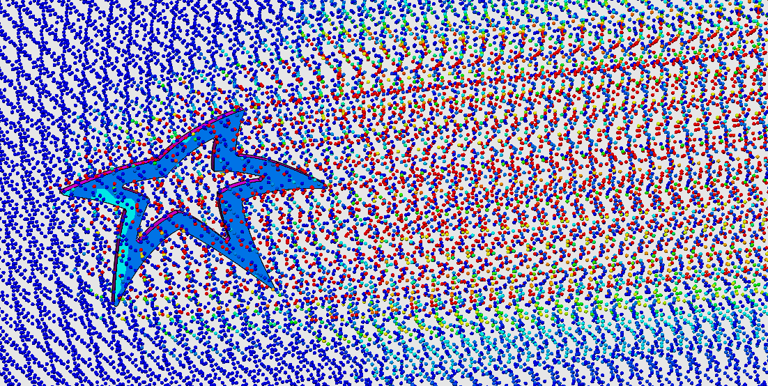
Mark Drlik is the StarFish Medical Concept Development Manager for devices including diagnostic, therapeutic or drug delivery use. He created the cool looking medical device CFD simulations (image and movie clip) for this article.
Images: StarFish Medical