Resource Centre
Discover a wealth of knowledge and insights from the experts at StarFish Medical. Our Resource Centre offers product development tips, reviews of new and cutting-edge technologies, and in-depth articles on regulatory updates and compliance in medical device development.
-
Most medical devices were designed for clinical settings, not the patients and caregivers who increasingly rely on them at home. Here's what good home-use device design actually requires.
-

How do you measure comfort in medical device design? Explore the tools, scales, and study design principles that turn a subjective experience into actionable design data.
-

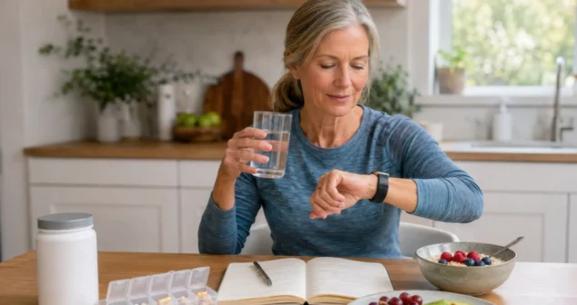
Gathering health data has enormous value for spotting risks, improving care, and advancing science. The problem isn't capturing the data. The problem is how we choose to present it and who we're really serving when we do.
-

Nick and Nigel break down the acronym, the biology behind it, and why resistance to this particular antibiotic class matters more than most people expect.
-
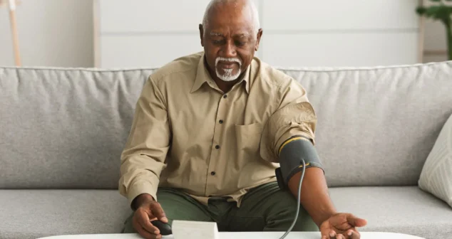
Connected health devices are multiplying fast. We examine the gap between remote monitoring's promise and its reality.
-
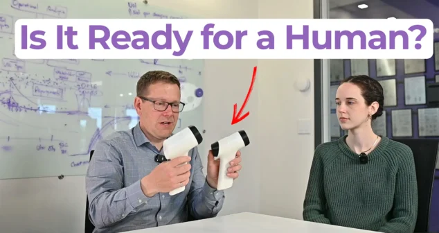
Ariana and Mark walk through what separates a clinical prototype from a proof-of-concept build, what determines how much testing and documentation you actually need, and where the regulatory line between significant risk and non-significant risk falls.
-

In this episode of Bio Break, Nick walks through both patent types after receiving two of his own in the mail, one of each, from the USPTO.
-

Scott Phillips sits down with Mickey Urdea to examine what actually distinguishes companies that reach commercial outcomes from those that do not.
-
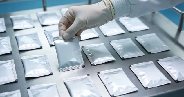
Nigel Syrotuck breaks down the realistic medical device V&V cost and schedule for terminally sterilized devices, picking up after design freeze and walking through each major phase of the process.