Medical device color management options
Why Colour-rendering Accuracy is Critical for Full-Colour Medical Device Color Management
“A picture is worth a thousand words.” That truism is no-less apt when it comes to medical devices, particularly when an accurate record or real-time presentation of tissue appearance is key to appropriate diagnosis and treatment.
Colour-rendering accuracy is often a critical aspect of the image: whether the device is in use during surgery, or enabling remote diagnosis, it’s important that the images it produces look like they would if the viewer were looking at the sample with their bare eye. Thus, medical device color management is something the medical-device designer needs to keep in mind whenever their product involves a true-colour imaging modality. As we shall see, the question of “true” colour is somewhat subtle.
To provide some idea of the subtlety, imagine that you’re walking to lunch outside with a friend wearing a white shirt. Then, you enter a quaint restaurant lit entirely by incandescent tungsten-filament light bulbs. Your friend’s shirt is “white” because it reflects all colours. However, the colour content of the noontime light outside is radically different than that of the incandescently lit restaurant, so the light reflected off your friend’s shirt is also radically different in the two environments. Yet your eye perceives the shirt as “white” in both circumstances! The same is true for colours other than white, as well.
The process by which your visual system recognizes and enforces this uniformity of perception is complex, and results from the interplay of visual-system components all the way from the eye’s cone-cell sensors, through multiple neural pathways, to the visual cortex. And the process applies not just to neutral (equally-reflective) white (and grey) objects but to all colours. However, this natural human adaptation provides challenges when we acquire images taken under one lighting condition, but view them under different illumination.
Reproducing colour accurately in digital images, then, requires correcting for differences in illumination conditions during acquisition and viewing for differences as well as for colour sensitivity between the human eye and the camera sensor.
When it comes to colour reproduction – or “white-balancing” your image – a medical-device designer has 5 basic medical device color management options:
1. Rely on the built-in white-balance capabilities of the camera.
If your illumination source spectrum is well-reproduced by a “standard” source (e.g. noontime sunlight, a “standard” fluorescent lamp, or possibly even a “popular” illumination LED, for recently released cameras) the camera designers likely have included custom white-balance correction settings appropriate for their sensor sensitivities to red, green, and blue. If you are so fortunate as for this to be the case, then the problem is effectively solved (so long as your monitor is correctly calibrated)!
If the illumination source is not standard, then you could choose to use the “closest setting” on the camera. However, this is fraught with risk of poor colour-balance during device use. In particular, if the spectrum of your light source is significantly different from that of a “standard black-body”, your image will suffer from green/yellow/blue shifts in addition to blue/red shifts induced by e.g. differences between daylight and incandescent illumination[1].
More generally, your camera may have an “auto white balance” setting, which measures the average colour of the whole scene and – under the assumption that the scene contains objects of many shades and hues – assumes the resulting “overall colour” is a neutral tone consisting of equal amounts red, blue, and green light. The camera firmware or software can then perform a white-balance operation before the image gets saved. However, in many medical-device applications it is unlikely that the image contains a broad spectrum of colours: think images of human tissue or the human retina, where the predominant colours are of reddish hues.
2. White-balance based on the “average colour” of the scene.
Even if the camera does not have an “auto white balance” setting, you can still manually apply the same process using external software tools. This approach suffers from the same limitations in applicability as the internal camera auto-balance functionality.
3. Find a “white” object in the image, and white-balance based on that object.
If you can count on your images to contain a white object, then you can manually apply white-balance correction based upon the recorded red, green and blue levels of this object as captured by your sensor (taking into account its own white-balance settings). Indeed, many photo-manipulation programs have “colour-picker” tools that can automatically do the math and corrections for you!
However, this approach has similar constraints as the “average colour” technique: many medical images do not contain any object with a neutral (white) reflectivity profile.
4. Take a “reference image” of a known-white object under imaging illumination conditions, and white-balance based on that image.
If the imaging illumination conditions are well-controlled, the white-balance settings to make that reference object “look” white are then sufficient to white-balance any image under those illumination conditions. These values can then be applied in software to any subsequent image; if you’re in control of the camera firmware or have a good working relationship with your camera-builder, you could also implement or request a “custom white balance” setting appropriate to your light source.
5. Record the spectrum of the illumination source, and white-balance based on that spectrum and your sensor specifications.
This approach is the lowest-level one: you will have to do the math yourself to work out the white-balance transformation (though you may be able to input this information to a piece of photo-manipulation software). However, it requires no assumptions, and no user intervention. Again, the correction can be applied in software or in firmware (assuming you have direct or indirect access to firmware).
For the last four approaches, it is imperative that the white-balancing be performed on RAW-format images, rather than JPEGs or other lossy image formats. The conversion from pixel information to JPEG entails compression algorithms and white-balance decisions largely outside the control of a medical-device designer. A number of tools for working with RAW images are listed in the “Further Resources” section below. White balance assumptions are usually included in the RAW image file as separate metadata – so it is possible to work with bare pixel counts, rather than having to “un-correct” the camera’s white-balance settings and then “re-correct” as appropriate to your light source.
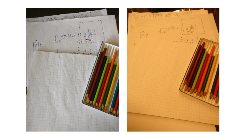
To understand white-balancing in more detail, let’s return to the example of your friend’s white shirt. Suppose, for example, you could record an image that exactly recorded all the wavelengths of light reflected off the shirt while inside the restaurant, and exactly reproduce that distribution of wavelengths upon demand. If you looked at the displayed image when you were back outside, your friend’s shirt would look very much like the white notepad in Figure 1b. (My friend brown-bagged their lunch, so I had to take recourse to a “still life” photograph that only an engineer could love…)
Your friend’s shirt would appear to have an orange tint (like the notepad in Figure 1b) because, in a noontime lighting environment, your visual system “expects” white objects to reflect a particular ratio of blue:green:red energies – a ratio different than that reflected when the shirt image was taken in the restaurant. Other colours are similarly shifted, as evidenced by the pencil crayons in Figure 1.

Figure 1: (left) Colours in an image taken under lighting conditions equivalent to noontime sunlight appear “normal” when viewed on a standard (sRGB) colour monitor. (right) Without proper white-balancing, the same objects appear “orange-shifted” when imaged under lighting conditions equivalent 3000 K incandescent illumination.
To flesh this out, we need to understand a bit about the distribution of “colours” in noontime sunlight and light from an incandescent bulb. To eliminate ambiguity of exactly the sort this blog is about, I’ll couch my description in terms of the wavelength of light. If we look at light with a single wavelength – think light from a laser pointer – then short wavelengths (approximately 400 nm to 500 nm) appear blue, medium wavelengths (approximately 500 nm to 600 nm) appear green or yellow, and longer wavelengths (approximately 600 nm to 650 nm) appear orange or red.
The Sun is a very hot ball of glowing gas which gives off a spectrum of colours that’s reasonably well-described as a smoothly varying “blackbody distribution[2];” the same is true of the hot filament inside an incandescent light. This type of spectrum is typical of the light given off by any hot object: from an orange glowing ember, to a red-hot poker, to a glowing tungsten filament in an incandescent light bulb, to a piece of white-hot steel fresh from the forge. The hotter the object, the greater the degree to which it gives off bluer light. Figure 2 shows a blackbody spectrum for an object at 6500 K (approx. 6230°C or 11250°F) – typical of the spectrum outside at noontime – and for a cooler object at 3000 K (approx. 2730° C or 4940° F) – like the filament in a tungsten light[3].

Figure 2: The spectral distribution (and associated colour distribution) of a “6500 K black-body radiator” like the Sun (left) and a “3000 K black-body radiator” like an incandescent bulb (right). (Images produced using the colour package)
From these graphs, we can begin to understand the differences between the light reflected by our friend’s shirt (or my notepad) outside vs. inside. When outside, the light reflected by a white object is more-dominated by blue wavelengths of light. On the other hand, the inside light reflected by the same object is more-dominated by red wavelengths. If our “outside eyes” are acclimatized to expect white objects to reflect blue-dominated light, then the exact reproduction of the light coming from the shirt when imaged inside will be blue-deficient – i.e. the shirt will look reddish or orange. The same holds true for any other colours displayed by our “exact reproduction device.”
You can imagine the confusion this colour shift could cause for a medical professional with years of “eyeball experience” in their discipline. Thus, colour correction is vital in a medical device.
Given the above, we can see that accurate colour rendering involves three technical aspects of colour recording and reproduction:
Aspect 1: Correction for illumination conditions while viewing the displayed image (as in the example of “your friend’s shirt”).
Aspect 2: Correction for artifacts of subsequent image display due to the colour-rendering limitations of monitors.
Aspect 3: Correction for differences between a camera sensor’s colour sensitivity and that of the eye.
When it comes to a digitally acquired image, there are a number of factors that make the task slightly less daunting than it might otherwise be.
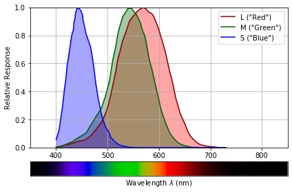
One of these simplifying factors is the response of human retinal cells to light of different wavelengths, shown in Figure 2. Colour-sensitive cone cells in the retina fall into three types: L, M, and S. Each cell responds to a different range of light colours (really: wavelengths). You can think of the cells as “red,” “green,” and “blue” sensitive but – given the substantial overlap between the L and M curves – this is really only a nominal concept.
The important point is that each cell type provides a single output whose magnitude is dependent on the total light of all wavelengths falling on the cell within its sensitivity range. Thus if two different illumination spectra produce the same L, M, and S outputs, they will produce indistinguishable colour sensations for the viewer. This indistinguishability greatly simplifies Aspect 2 of white balancing from our numbered list (above) – we don’t need our display to reproduce the detailed spectrum coming of our friend’s shirt, but only the L, M, S stimulus outputs induced by that spectrum.

Figure 3: Human L, M and S photoreceptor sensitivities as a function of the wavelength of light: a spectrum of visible light is shown below, for reference. (Images produced using the colour package)
A second simplifying factor is that the relationship between different colours is approximately linear. (Mathematically, the set of colours form a vector space.) This means that if we can get a white object to “look right” under our viewing illumination, the other colours in our image “come along for the ride.” It also means that if we can get the white balance right for a single image taken in specific lighting conditions and displayed in different specific lighting conditions, the same white balancing recipe will work for all other pictures taken and displayed in those respective conditions.
A final simplifying factor is the fact that most medical-device images are viewed on monitors, and monitor manufacturers have settled on displaying white objects as if they were illuminated by a 6500 K blackbody spectrum[4]. This simplifies dealing with Aspect 1 of white balancing: in terms of human eye response, it implies that we have a unique set of “white” L, M, S values to target for all images we take.
On the other hand, determining a white-balance recipe is complicated by several challenges. The first is the fact that even the best of display monitors are unable to reproduce all of the colours perceivable by the human eye: that is, they have limited colour gamuts. So even an image taken under 6500 K illumination and displayed on a 6500 K monitor will not be necessarily be capable of accurately representing all colours present in the scene.
Furthermore, if we image these objects under different illumination conditions, we will need to decide how to deal with shifting these colours to the hue they’d appear under 6500 K illumination: the monitor simply can’t display those hues! This artifact is an inherent limitation to white-balancing.
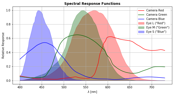
A more-tractable challenge is correcting for the differences between camera spectral response and those of the cones. The red, green and blue lines in Figure 4. show the spectral responsivity of a typical sensor – the detailed response varies sensor by sensor and manufacturer by manufacturer. Also shown, for comparison, are the L, M, S responses – we can see the two sets of responsivity curves are quite distinct.

Figure 4: Red-, green-, and blue-channel responses as a function of light wavelength, for a typical high-performance CMOS camera (lines). Human L, M and S photoreceptor sensitivities versus wavelength of light are shown for comparison (shaded curves).
However, this challenge simply amounts to finding the matching (Rsensor, Gsensor, Bsensor) « (L, M, S) values, albeit for for the particular illumination condition in which your sensor acquires images.
Depending on which white-balancing option you choose, performing good white-balancing on your medical-device true-colour images may require acquainting yourself with some knowledge of colour science and using some matrix math. However, failure to perform good colour correction on these images will, at best, produce images that look glaringly aberrant and, at worst, may lead to inaccurate diagnoses or inappropriate treatment. It stands to reason, then, that considering your white-balancing needs and medical device color management technique is a key part of the design process.
Further Resources:
This list consists of a handful of open-source image/colour-manipulation packages that can enable you to “dip your feet in the waters” of white-balancing.
Python colour-science packages:
Open-source mage-manipulation packages capable of working with camera RAW-format images:
[1] Note that if you choose LED illumination (for cost or power-consumption considerations), the so-called “colour rendering index” of the LED refers to “colour rendering by the human eye” and not by your camera sensor!
[2]In the case of sunlight, the “pure” blackbody spectrum is altered by the absorption, emission, and scattering by atoms and molecules in the sun and in the Earth’s atmosphere
[3]The spectra for blackbody radiators are usually described with the radiators’ temperature expressed on the “Kelvin” temperature scale, rather than in degrees Celsius or Farenheit.
[4] Strictly speaking, the standard “D65 CIE illuminant,” but the differences are negligible for the sake of the current discussion.
Brian King is Principal Optical Systems Engineer at StarFish Medical. Previously, he was Manager of Optical Engineering and Systems Engineering at Cymer Semiconductor, Brian was an Assistant Professor at McMaster University. Brian holds a B.Sc in Mathematical Physics from SFU, and an M.S. and Ph.D. in Physics from the University of Colorado at Boulder.
Images: StarFish Medical

