Medical Device Image Sensor Considerations
Produce the most high-fidelity images and/or cleanest data possible
Part 3: Types of Image Sensors
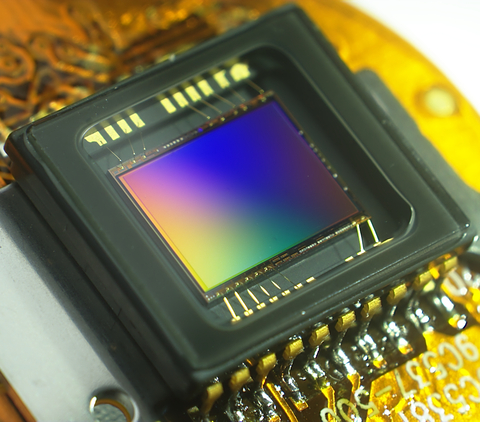
Camera sensors are common components of medical devices. This blog covers various types of medical device image sensors. Generally, image sensors consist of an array of photosensitive pixels. In typical camera applications, such sensors measure the spatial pattern of light focused by a lens (i.e., an image). In some applications (for example, digital holography or shadow imaging), image sensors may be used without a lens.
This blog is the third in a series discussing things to consider when choosing an image sensor for a medical device camera. The first entry in this blog series covered camera sensor resolution and pixel size. The second entry covered considerations related to incident irradiance, exposure time, gain, and frame rate, and their impact on figures of merit such as dynamic range and signal-to-noise ratio.
CCD versus CMOS Medical Device Image Sensors
Most images sensors are either charge-coupled devices (CCD) or complementary metal-oxide semiconductor (CMOS) arrays. These sensors operate using different electrical mechanisms and are fabricated by different methods, and as such they tend to each have their own advantages and disadvantages.
In CCDs, an array of photosensitive capacitive sites (i.e., pixels) each accumulate charge proportional to light incident upon them. After the exposure to light has been completed, a control circuit is used to move the charge from each pixel into a charge amplifier, which converts the accumulated charge into a voltage. Once the charge collected on each site has been measured, an image can be generated.
In CMOS sensors, each individual pixel contains a photodetector (usually a photodiode – i.e., a diode that generates current when light is incident upon it) with a circuit containing a number of transistors. The circuit controls the pixel’s functions such as activating or resetting the pixel, or reading its signal out to an analog-to-digital converter.
Historically speaking, CCD-based sensors have had a lower noise level, a higher single-shot dynamic range, a more uniform response to light across the entire sensor, and greater sensitivity in low light due to a higher pixel fill factor. On the other hand, CMOS sensors have been capable of much higher frame-capture rates, lower power consumption, higher responsivity, and were less expensive at volume [1]. This led to CMOS sensors being preferred in low-cost/low-power applications such as smartphone and other consumer cameras, and in cases where high frame-capture rates are needed. CCD cameras have had performance advantages in cases where high sensitivity, low noise, and/or high uniformity are needed, such as certain low-light applications.
It must be noted that the quality of CMOS sensors has developed rapidly over the last few years and the advantages in performance that CCDs have had historically are diminishing. Some CCDs still have advantages in dynamic range, uniformity, and IR performance and are preferred for some scientific and industrial applications [2]. Nonetheless, CMOS-based detectors are available that are suitable for most applications, in addition to those for which they have been historically preferred. Ultimately the required specifications and cost of the sensor are what must be considered.
Monochromatic versus Colour
Both CCD and CMOS sensors come in colour and monochromatic (also called “black and white” though the sensors actually produce images in greyscale) varieties.
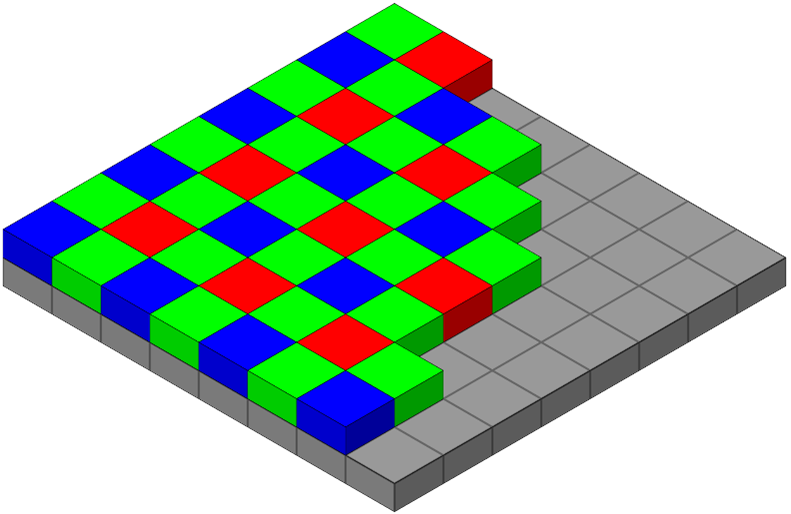
In monochromatic cameras, the image is obtained simply by recording the amount of light captured by each pixel. In most colour cameras, an array of red, green and blue (RGB) colour filters (a Bayer filter) is placed over the pixels that restricts the light collected by each pixel to a certain range of wavelengths (colours)[1]. Based on the amount of light collected by each of the filtered pixels, the colour image is inferred based on the collected pattern, in a process called demosaicing [3].

Colour camera sensors are useful because they provide a simple way to capture colour images. They can also be used to approximate a monochromatic camera sensor in software (for example, by only displaying data from the green channel, or by converting a captured image to greyscale). However, they have some disadvantages compared to monochromatic cameras, which are often the superior choice when colour is not needed.
Each of the individual pixels on a colour sensor does not receive the full RGB information. This fact, along with the demosaicing process, results in an image whose effective resolution is slightly less than that of a monochromatic camera with the same size and pixel count [4]. Monochromatic cameras also have higher a greater response to a given incident irradiance than colour cameras, as none of the light incident on the pixels is filtered out.
In cases where colour images are needed along with the advantages of a monochromatic sensor, alternative methods can be used. One method is to take individual red, green and blue images with a monochromatic camera using full-frame colour filters, and to reconstruct the true colours by combing the three images. Another method is capture RGB images simultaneously using three sensors with a special prism used to direct each colour range to one of the three sensors (sometimes called a 3CDD camera [5], though CMOS sensors could also be used).
Other Medical Device Image Sensors
Image sensors can take several additional forms for non-visible light ranges and other special applications.
X-ray images can be captured using digital radiography sensors. The most common type of such sensors are flat-panel detectors (FPDs) [6]. These detectors come in “direct” and “indirect” varieties. Similarly to conventional image detectors, direct FPDs convert X-ray light directly to charge (but use different materials), and the generated charge is read out by a pixel array. Indirect FPDs first use a scintillator to convert the incident X-rays to visible light, which is then measured by a pixel array.
Thermal cameras measure infrared (IR) light and use it to infer temperature. A number of technologies exist for making such cameras. One example is a microbolometer array, which consists of an array of specialized pixels. The top layer of these pixels is a material that changes resistance when heated by IR light. The change in resistance is then measured by underlying electronics to infer temperature. The array of pixels then generates a thermal image, showing the spatially-resolved temperature of the imaged object.
Finally, it is possible to generate an image of an object without using a pixel array-based sensor at all. Single-pixel cameras are a type of “camera” that operate by measuring (with a single photodiode, for example) the amount of light reflected from each of a series of patterns projected on the object. In the most straightforward case, the pattern is simply a focused point of light that is scanned over the surface of the object. By mapping the amount of reflected light to the location from which it was reflected, an image of the object can be inferred.
Conclusion
Selecting and using medical device image sensors requires the consideration of many factors. In this blog series, we have discussed some of the most important aspects such as resolution, pixel size, dynamic range, exposure time, and frame rate, as well as the most common types of image sensors and their advantages and disadvantages. With proper attention to these factors, a camera sensor can be chosen and configured to produce the most high-fidelity images and/or cleanest data possible.
References
| [1] | Edmund Optics, “Imaging Electronics 101: Understanding Camera Sensors for Machine Vision Applications,” [Online]. Available: https://www.edmundoptics.com/knowledge-center/application-notes/imaging/understanding-camera-sensors-for-machine-vision-applications/. [Accessed 9 November 2020]. |
| [2] | Teledyne Imaging, “The Future is Bright for CCD Sensors,” 22 January 2020. [Online]. Available: https://www.teledyneimaging.com/media/1299/2020-01-22_e2v_the-future-is-bright-for-ccd-sensors_web.pdf. [Accessed 19 November 2020]. |
| [3] | Wikipedia, “Demosaicing,” [Online]. Available: https://en.wikipedia.org/wiki/Demosaicing. [Accessed 12 November 2020]. |
| [4] | Red Digital Cinema, “RED 101: Color vs. Monochrome Sensors,” [Online]. Available: https://www.red.com/red-101/color-monochrome-camera-sensors. [Accessed 9 November 2020]. |
| [5] | Wikipedia, “Three-CCD camera,” [Online]. Available: https://en.wikipedia.org/wiki/Three-CCD_camera. [Accessed 12 November 2020]. |
| [6] | Wikipedia, “Flat-panel detector,” [Online]. Available: https://en.wikipedia.org/wiki/Flat-panel_detector. [Accessed 21 6 2021]. |
[1] Each pixel on a colour image sensor has either a red, green, or blue colour filter, which is different than the way colour is handled by the pixels on a typical monitor. Each individual pixel on a monitor has a combination of red, green, and blue subpixels.
Ryan Field is an Optical Engineer at StarFish Medical. Ryan holds a PhD in Physics from the University of Toronto. As a post doctoral fellow, he worked on the development of high-power picosecond infrared laser systems for surgical applications as well as a spectrometer from home materials.
