Making an Ophthalmic Instrument Safety Assessment
Ophthalmic Instrument Safety Assessment
Many ophthalmic instruments expose the eye to light – either for diagnostic or treatment purposes (or both). Such ophthalmic medical devices are expected to conform to the relevant light-hazard protection standard (see “Incoherent-Light Hazard Classification for Medical Devices” for further desciption of these standards).
Generally, assessments will be performed by a qualified testing laboratory. However, as with all external testing, it is advisable to “pre-screen” your device before shipping it to the labs, so you can identify and mitigate any deficiencies that crop up in the gap between design and build reality. In this blog, we’ll discuss approaches to performing this pre-screen Ophthalmic Instrument Safety Assessment testing in-house.
The two main light-hazard protection standards are ANSI Z80.36(2021) for FDA clearance and ISO 15004-2(2024) which is applicable to certification in Europe. Note that regulators take a risk-based approach to clearance. So – though they may be most familiar with the standards pertaining to their geographic region – they may be willing to consider risk assessments predicated upon either. Worldwide, regulators will likely require assessment one of these two standards.
For concreteness, we’ll consider the measurement requirements and guidance laid out in ISO 15004-2:2024. Some of the detailed dimensions and limits are different when testing per ANSI Z80.36:2021, but the guidance annexes are very similar in the scenarios common to the two standards.
Though one should always refer to the relevant standard, our hope is that this blog will facilitate interpreting those standards for CTOs, engineers, technicians and others who will be guiding new ophthalmic medical devices through the safety certification process. That way, a medical-device developer will have confidence before they send their ophthalmic device for official testing.
Ophthalmic Instrument Safety Assessment Overview
As discussed in the Incoherent-Light Hazard Classification blog, light-hazards can be grouped into anterior-segment and retinal hazards. One can also categorize each hazard as either a “photochemical” or “thermal” hazard. Generally, the photochemical hazards are – as the name suggests – due to chemical changes driven by the light exposure. Generally, the risk is time-independent and proportional to only the total dose received per unit area: that is, the total fluence falling on the relevant part of the eye.
On the other hand, thermal hazards are due to tissue heating. Thus, there is an implicit thermalization time scale built into the limits – and this thermalization time scale generally depends on both the size of the illuminated area and on the exposure duration. The former dependence is due to limitations in heat conduction out of the boundary, whereas the latter accounts for whether the process is regular, thermally confined, or thermally and photoacoustically confined thermalization. Generally, evaluating thermal limits is more complex than evaluating photochemical ones.
The equipment required for the pre-scan can be as simple as a calibrated optical power meter, a spectrometer (or reliable data sheet that provides the light source’s spectrum), and select apertures (used to set averaging areas or averaging solid angles, or both). For pulsed instruments, a pulse-energy meter should be used. For pre-scans, a power meter, combined knowledge of the pulse-to-pulse energy stability and the pulse-repetition rate can serve as an alternative.
In the following, it’s worth mentioning that – in general – there are two size scales to keep in mind (three, when we start to evaluate retinal hazards!):
- The size of the illuminated area on the eye. This will be less-important for photochemical hazards, but will play a role in evaluating thermal hazards anterior and posterior/retinal.
- The averaging size for the measurements. In general, the distribution of light on the eye will not be uniform, and there may be localized areas of higher power or energy density. However, if these “hot spots” are small, their impact may be “smoothed out” by the body’s response to the light. The standards take this into account, by specifying minimum averaging sizes when performing light-level measurements.
Measurement Protocols
In general, the hazard calculation weights the spectral time-integrated (ir)radiance E (in mJ/(cm²·nm) or mJ/(cm²·sr·nm)) by a spectral weighting function (which may have value 1.0 for all wavelengths for some hazards). This “effective hazard” is then compared to the hazard limit appropriate to the hazard type, spot size (if applicable) and time scale (if applicable).
In practice, one measures optical power (or optical energy, for pulsed sources) in a well-defined area to determine peak irradiance (or fluence). For retinal hazards – for which the retinal spot size is assumed to be proportional to the solid angle of the source or source region – an averaging solid-angle may also be defined, but the measurement performed is still power (energy) in a well-defined measurement area.
From the detected power (energy), one then calculates the equivalent irradiance or radiance (fluence or time-integrated radiance), weights by the spectral distribution of energy and the weighting function, and finally compares to the hazard limit.
Personally, we prefer to pre- calculate in the following way:
- Calculate the area-normalized spectral distribution (from data sheets and/or spectrometer measurements).
- Calculate the spectral sum of the normalized spectrum multiplied by the appropriate weighting function taken from the standard.
- Divide the hazard limit by said quantity to determine the effective hazard limit for that particular source.
- Multiply by aperture areas to predict ahead of time the detected power corresponding to the effective hazard limit.
Following this methodology gives instant feedback in the lab: what fraction of the Group 1 or Group 2 hazard limit the source measured yields. We then perform the calculations in reverse, as a double-check and to ensure compliance with the wording of the standards.
To make that particular approach more explicit, if measuring a CW source power with normalized spectrum ![]() over a time frame
over a time frame ![]() , with hazard limit
, with hazard limit ![]() , the standard would call to calculate:
, the standard would call to calculate:

in which ![]() is the appropriate hazard-weighting function.
is the appropriate hazard-weighting function.
Re-express this first as:

in which ![]() is the spectral distribution of the source emission normalized to unit area.
is the spectral distribution of the source emission normalized to unit area.
Finally:
![]()
If ![]() is evaluated by measuring optical power
is evaluated by measuring optical power ![]() over an aperture stop area
over an aperture stop area ![]() , calculate:
, calculate:
![]()
Note that one should always measure the power in the plane at which corneal, iris, or pupil of the eye will be located during device use, as appropriate to the hazard under consideration. One should then move the power meter in that plane to find the spot of maximum power reading in that plane.
Anterior Segment
The anterior segment assessments may be broken up into thermal and photochemical. We’ll treat them in order.
Photochemical Hazard: ![]()
To evaluate this hazard, the spectrum should be weighted by the UV Radiation Hazard Weighting Function ![]() , between wavelengths 250 nm and 400 nm at which the source has spectral power. The measurement should be performed with a 3 mm diameter aperture stop immediately in front of the power/energy meter (which itself should therefore have an acceptance diameter > 3 mm). See Figure 1 (a) for one example of how to mount such an aperture stop. The aperture stop should be located in the corneal plane when performing the measurement. It is not necessary to evaluate this hazard for total exposures < 1 ns (other limits are more restrictive).
, between wavelengths 250 nm and 400 nm at which the source has spectral power. The measurement should be performed with a 3 mm diameter aperture stop immediately in front of the power/energy meter (which itself should therefore have an acceptance diameter > 3 mm). See Figure 1 (a) for one example of how to mount such an aperture stop. The aperture stop should be located in the corneal plane when performing the measurement. It is not necessary to evaluate this hazard for total exposures < 1 ns (other limits are more restrictive).
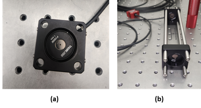
Figure 1 (a) A measurement configuration for determining anterior-segment hazards. An aperture stop is placed in front of the detector to define the measurement/averaging area (in this case, with diameter 1 mm appropriate to some of the anterior-segment thermal hazards). In this picture, the power-meter head is screwed into the back of the SM1 thread of the 30 mm cage plate and so is not visible (though its cable is). Note that the detector active-area diameter must be larger than the aperture stop diameter. (b) A measurement configuration for determining radiance, relevant to determining retinal hazards by measurements. In this case, a 7 mm aperture stop is placed directly in front of the power meter (mounted directly to the back of the back cage plate); the averaging solid angle of 0.018 rad is defined by the diameter 300 µm of the field stop (mounted in the front cage plate) and the 16.6 cm distance between the field stop and aperture stop (located in the back cage plate, immediately in front of the detector).
Thermal Hazards: ![]() ,
, ![]() , and
, and ![]()
 – 250 nm to 315 nm: This hazard should be evaluated separately from the same hazard at longer wavelengths (see below). Use a 1 mm diameter aperture stop directly in front of the power/energy meter, located at the plane in which the cornea will be located in use. It is not necessary to evaluate this hazard for exposures > 10 s (other limits are more restrictive).
Note that the following 3 hazards need only be evaluated if the iris is not exposed!
Also note the none of these 3 hazards has a spectral weighting function. (Alternately, the weighting function is 1.0 for all wavelengths!)
 – 315 nm to 400 nm: For exposures < 25 seconds, place a 1 mm diameter aperture stop directly in front of the power/energy meter, and measure in the corneal plane. For exposures > 25 s, use a 3.5 mm diameter aperture stop instead.
 – 400 nm to 1200 nm: Again, use a 1 mm diameter aperture stop for exposures < 25 seconds, but a 3.5 mm diameter aperture stop for longer durations. Measure in the corneal plane. However, see Item 5., below, for the case in which the beam has diameter ≤ 2 mm at any point from the anterior surface of the cornea to the posterior surface of the crystalline lens.
 – 1200 nm to 2500 nm: Again, use a 1 mm diameter aperture stop for exposures < 25 seconds, but a 3.5 mm diameter aperture stop for longer durations. Measure in the corneal plane.
- – 400 nm to 1200 nm, small beams: For small beams (diameter < 2 mm anywhere between the front of the cornea and the back of the lens), both the measurement and the limit are different than those listed in Item 3., above. In this situation, use a 1 mm diameter aperture stop for all applicable times and place it in the narrowest point in the beam. In the small-beam case, this limit must be evaluated in addition to
 , below.
 - – 320 nm to 1400 nm: This hazard appears to be new to the 2024 version of ISO-15004. The measurement is straightforward: measure the maximum power received in a 0.200 mm diameter aperture stop placed in the plane of the iris when the instrument is in use. The hazard limit (or effective hazard limit) calculation, however, requires one to know or measure the iridial spot size. For a diffuse source (such as an uncollimated LED), this would be the iridial diameter (95th-percentile diameter 12.34 mm – however, this would not account for energy passing through the pupil). For a collimated circular beam it will be the beam diameter, and for a focused spot it will be the spot diameter on the iris. As with the retinal limits discussed below, there are 2 caveats to this iridial spot size:
- For asymmetric beams, the spot size
 is taken to be the mean of the spot length in the two principal directions.
 - If the spot size is smaller than than 0.200 mm, the spot diameter is taken to be 0.200 mm. (This would presumably also apply to the short dimension in Caveat 1.) Note that this lower limit to spot size is automatically taken into account by the aperture stop for the measurement, so that one may calculate effective peak irradiances by simply averaging the power detected by the aperture stop area.
Retina (Posterior Segment)
Overall Approach
Evaluating retinal hazards is most straightforward if, from the optical design, you have a confident idea of the extent ![]() of the light source’s image on the retina If you don’t, however, you must able to relate retinal spot size and irradiance/fluence based on measurements performed outside the eye.
of the light source’s image on the retina If you don’t, however, you must able to relate retinal spot size and irradiance/fluence based on measurements performed outside the eye.
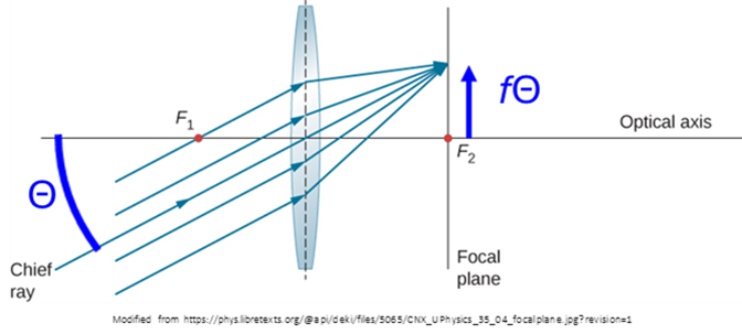
The key concept to understanding the recommended approaches in the latter situation is this: the maximal hazard will occur with the smallest retinal spot size, and this smallest size occurs when the eye focusses the light source onto the retina. That is to say, the eye acts as a lens with the retina at its effective focal length ![]() 17 mm. But a lens turns incoming ray angles
17 mm. But a lens turns incoming ray angles ![]() into spots with transverse location
into spots with transverse location ![]() (see Figure 2) at the focal plane of the lens. What this implies is that:
(see Figure 2) at the focal plane of the lens. What this implies is that:
- The retinal spot size is proportional to the angular divergence of the light hitting the anterior segment:
 , in which
  represents said angular divergence, and
  17 mm.
Under normal conditions, the eye exhibits a variety of ongoing motions: jitter, drift, microsaccades and saccades[1]. The hazard is calculated using the maximum irradiance or fluence on the retina. However, these motions have the effect of smearing out any localized spots of high power/energy over timescales commensurate with the motional times scales. As discussed in the Overview, the standard incorporates these effects by allowing one to average power/energy over a minimum spot size on the retina. ISO 15004-2:2024 imposes minimum retinal averaging area sizes of:
- 0.180 mm, for a general viewing situation.
- 0.030 mm, for an immobilized eye (e.g. one undergoing applanation).
Just as with the source size dr discussed in the previous paragraph, retinal size is proportional to the divergence of the beam incident on the eye. So the above retinal averaging sizes correspond to divergence angles incident on the eye of (Annex D, Table D.1):
- 0.0106 rad = 0.61° = (0.180mm)/(17.0 mm).
- 0.0018 rad = 0.10° = (0.030mm)/(17.0 mm).
This implies that the minimum averaging field of view that must be considered for retinal-hazard calculations is given by the above formulæ.
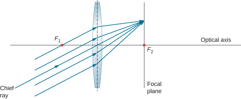
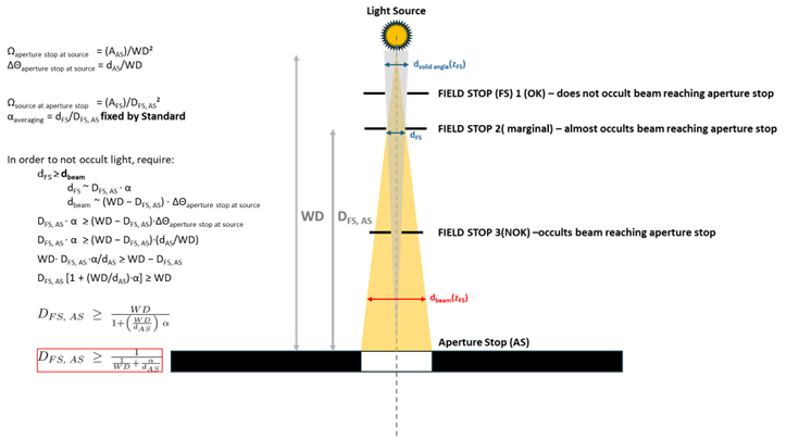
One defines the field of view by introducing an additional, field, stop of diameter ![]() some distance
some distance ![]() from the aperture stop that defines the averaging area on the detector. The field of view is then determined by
from the aperture stop that defines the averaging area on the detector. The field of view is then determined by ![]() (solid angle
(solid angle ![]() ). However, in setting
). However, in setting ![]() and
and ![]() , one must be careful not to block optical power that would otherwise reach the detector (see Figure 3). If that is the case, then one should use the size of the beam at the detector as the “effective aperture size” when calculating irradiance or radiance (see below).
, one must be careful not to block optical power that would otherwise reach the detector (see Figure 3). If that is the case, then one should use the size of the beam at the detector as the “effective aperture size” when calculating irradiance or radiance (see below).
Having set the measurement configuration, one may then evaluate the retinal irradiance/fluence by measuring corneal radiance/time-integrated radiance.
1, Diffuse source: Place the field stop the calculated distance from the aperture stop and measure the transmitted power to determine the radiance in the defined solid angle (determined by field stop area and separation) and defined area (determined either by the aperture stop size or “effective aperture stop size” if the field stop blocks some light in ).
In this case:![]()
![]()
in which ![]() = 17.0 mm is the distance from the lens to the retina, and
= 17.0 mm is the distance from the lens to the retina, and ![]() is the beam area on the pupil.
is the beam area on the pupil.
From the above two equations:![]()
![]()
and in terms of the optical power measured at the pupil plane:![]()
In the case in which the aperture stop diameter can be taken to be the pupil diameter so that ![]() , this simplifies to:
, this simplifies to:
![]()
Thus, in order to satisfy the Group 1 or Group 2 limits ![]() , we must have
, we must have
![]()
and if ![]() , this becomes:
, this becomes:
![]()
To reiterate, this last equation only holds if the working distance allows the aperture stop diameter to be set equal to the pupil diameter of 7 mm.
2. In the case of a compact beam, the calculation is similar, but now the irradiance should be determined by dividing the received power by the beam area ![]() . But by the same token the solid angle subtended by the beam at the retina will also incorporate
. But by the same token the solid angle subtended by the beam at the retina will also incorporate ![]() as
as ![]() .
.
Then, again, we have:
![]()
and the limitation on measured optical power again becomes:

With the overall approach to retinal measurements described, now consider the two retinal hazards.
Photochemical Hazard: ![]() or
or ![]()
This hazard is expressed as either ![]() or
or ![]() . The difference between the two is whether the crystalline lens is present and fully formed (i.e. anyone over the age of 2 years who has an intact lens) or not. In the former case, the “Blue light photochemical hazard function”
. The difference between the two is whether the crystalline lens is present and fully formed (i.e. anyone over the age of 2 years who has an intact lens) or not. In the former case, the “Blue light photochemical hazard function” ![]() is used; in the latter, the “Aphakic photochemical hazard weighting function”
is used; in the latter, the “Aphakic photochemical hazard weighting function” ![]() . In general, a 0.180 mm averaging size is used on the retina (
. In general, a 0.180 mm averaging size is used on the retina (![]() = 0.0106 rad). For immobilized eyes, a 0.030 mm averaging size is used (
= 0.0106 rad). For immobilized eyes, a 0.030 mm averaging size is used (![]() = 0.0018 rad).
= 0.0018 rad).
If the beam spot on the retina is uniform (i.e. if the radiant intensity on the pupil is uniform) and has a spot size greater than 1 mm (~0.0589 rad divergence onto the pupil), then it is permissible to average the retinal irradiance (incident radiant intensity) over any retinal spot size smaller than the beam.
Thermal Hazard: ![]() or
or ![]()
Because of the different thermal time scales mentioned in the introduction, there are 4 retinal-spot-size dependent “hazard limit regimes.” For some of these regimes, the retinal spot size is part of the hazard-limit evaluation. Thus, one must determine the retinal spot size in order to appropriately calculate the limit.
The most straightforward way to do this is to apply knowledge of the optical model for the system; for example, a raytrace that follows the light all the way through a model eye[2]. Alternately, one can calculate the angular subtense of the source as viewed from the eye in its nominal location, then apply the formula discussed above to convert angular subtense at the pupil to retinal spot diameter: ![]() . As an additional alternative, one can place a 17 mm focal-length lens in the nominal in-use eye location to simulate the optical effect of the eye. One can then record the image irradiance/fluence distribution on a sensor (e.g. CMOS camera).
. As an additional alternative, one can place a 17 mm focal-length lens in the nominal in-use eye location to simulate the optical effect of the eye. One can then record the image irradiance/fluence distribution on a sensor (e.g. CMOS camera).
For the smallest retinal spot sizes, the hazard limit is expressed in terms of total dose received (in Joules) rather than fluence (J/cm²).
Finally, as with the retinal photochemical hazard, if the beam spot on the retina is uniform and has a spot size greater than 1 mm (~0.0589 rad divergence onto the pupil), then it is permissible to average the retinal irradiance over a retinal spot size smaller than the beam.
Ophthalmic Instrument Safety Assessment Conclusion
The information contained above is taken from ISO 15004-2:2024. However, in that document, said information is scattered in various tables and different Annexes. The examples in Annex E put the information to practice: however, those examples are sometimes unclear as to the assumptions made and the particular approach being applied (and why!). Our hope is that this blog will provide an alternate resoruce for those wishing to perform preliminary ophthalmic light source assessments in-house. That way, medical device designers can avoid unpleasant surprises when their prototypes make it to the testing house!
The optics team at StarFish Medical are always interested in hearing about new applications and devices the use optical technologies. Please contact us to discuss your project.
[1] Rolfs, Vision Research 49, 20, 2415 (2009)
[2] e.g. Liou and Brennan, “Anatomically accurate, finite model eye for optical modeling,” Journal of the Optical Society of America A 14, 8, 1684 (1997); https://doi.org/10.1364/JOSAA.14.001684
Brian King is Principal Optical Systems Engineer at StarFish Medical. Previously Manager of Optical Engineering and Systems Engineering at Cymer Semiconductor/ASML, Brian was an Assistant Professor at McMaster University. Brian holds a B.Sc. in Mathematical Physics from SFU, and an M.S. and Ph.D. in Physics from the University of Colorado at Boulder. His research centered on implementing quantum information processing with trapped, laser cooled atoms – often single atoms confined in radiofrequency ion traps operating at ultrahigh vacuum.
Ryan Field is a Senior Optical Systems Engineer at StarFish Medical. Ryan holds a PhD in Physics from the University of Toronto. As a post doctoral fellow, he worked on the development of high-power picosecond infrared laser systems for surgical applications. He has worked in the medical device industry throughout his post-academic career and has worked on a diverse range of optical applications including fluorescence illumination systems, optical assays, diagnostic imaging systems, and ophthalmic laser surgery devices.