How Shear Stress and Residence Time Simulations Shape Safer Biological Fluid Handling Devices
The impact of shear stress is critical to effectively design medical devices that handle biological fluids such as proteins or cell culture media. For example, non-physiological shear stress (NPSS) on blood is a key factor because hemolysis (cell rupture) could occur due to accumulated stress. If this is applied to patients, this could lead to serious health outcomes, thus representing a clinical risk. Intravascular catheters, extracorporeal circuits, dialysis cartridges, and lab-on-chip diagnostics typically share one critical requirement: they must transport or manipulate blood without damaging it.
Two computational tools are instrumental in achieving this goal: shear stress modeling and residence time simulation. Together, they help engineers predict and prevent blood trauma, optimize flow paths, and reduce the risks of hemolysis and thrombosis.
Why Shear Stress Modeling Is Essential in Medical Device Design
Shear stress refers to the tangential force per unit area a fluid exerts on a surface as it flows. Biological fluids like blood or protein solutions are especially sensitive and can accumulate this damage over time.
In devices that channel blood, elevated shear stress can deform or even rupture red blood cells (RBCs), a process known as hemolysis. Additionally, high or oscillatory shear can activate platelets, potentially leading to thrombosis (clotting). Moreover, interfacial stresses in combination with high shear stresses can lead to protein denaturation or aggregation in protein solutions.
While blood can withstand moderate shear (typically < 100 Pa), designs that create abrupt changes in geometry – such as sharp corners or high-speed jets – often cause localized peaks in wall shear stress well above this threshold. Repeated or prolonged exposure to such forces accelerates cellular damage, compromising the diagnostic or therapeutic goal.
Using CFD Simulations to Model Shear Stress in Medical Devices
To identify and minimize risk of high-shear regions, we leverage the advanced capabilities of Computational Fluid Dynamics (CFD) simulations. An important input to model accurate phenomena is a fluid’s viscosity. Unlike water or air, which are Newtonian (linear correlations of viscosity and shear), blood is non-Newtonian, meaning its viscosity changes in a non-linear relationship with its shear rate. Accurate modeling requires use of advanced rheological models, such as:
- Carreau-Yasuda Model for blood and some protein solutions
- Population Balance Based Rheology (PBBR) Model for blood with capabilities in agglomeration and deagglomeration mechanics
- User-defined models for proprietary biologic formulations
Some of these models are more tailored to specific applications, each with their own advantages and limitations.
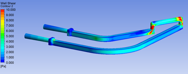
Wall Shear Stress (WSS) specifically refers to shear acting along the wall surface of the channel or lumen. High WSS contributes to hemolysis, platelet activation, and endothelial damage in implants and grafts, which triggers inflammatory responses. Additionally, localized shear spikes in proteins, such as monoclonal antibodies and enzymes – can cause aggregation or unfolding and can even rupture cell membranes or cell markers critical to cell function.
How Residence Time Analysis Improves Medical Device Safety
While shear provides discrete stresses applied to critical components of a fluid, residence time shows how long they are accumulated. This is critical to track, as regions of low flow velocity or recirculation can lead to:
- Clotting in blood-contacting zones
- Protein degradation due to high shear stress and prolonged exposure to air and heat due to recirculation
- Biofilm formation in slow-moving protein-rich fluids, leading to decreased performance of functionalized surfaces of diagnostic devices
- Assay inaccuracy from sample retention or reagent dilution
With CFD, we can simulate flow trajectories and visualize residence time with tools like:
- Lagrangian particle tracking or Scalar transport equations to calculate how long fluid parcels remain in specific regions
- Volume of Fluid (VOF) models for multiphase interactions
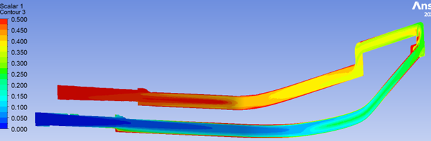
The results of these simulations can be presented as gradient colour maps or histograms, which allow visualization of residence times across the device.
A critical aspect ahead of setup is to configure the model to focus on design features that have higher risks to biological fluids, especially their impact on shear. Some examples include:
- Sudden expansions or contractions in the lumen
- Elbows or bifurcations
- Valve interfaces
- Syringe tips or needle ports
By adjusting curvature, tapering transitions, and smoothing surfaces, CFD helps mitigate WSS-related risks before a physical prototype is built.
Leveraging CFD Modeling for Regulatory Approval and Commercial Success
Regulatory agencies like the FDA are increasingly receptive to the inclusion of validated modeling data in medical device submissions. When supported by physical testing or peer-reviewed benchmarks, CFD analysis of shear stress and residence time can reduce the burden of physical testing, support risk mitigation strategies and accelerate approval timelines. From a business standpoint, this translates to shorter development cycles and fewer failed prototypes.
Conclusion: Safer Biological Fluid Handling Through Advanced Simulation
Shear stress modeling and residence time simulation empower us to predict risks of a biological fluid’s transit through a device. Poor design can damage cells, including blood clotting and protein aggregation, resulting in damage to biologic products or negatively affecting diagnostic performance. With CFD-driven shear stress and residence time analysis, these risks become visible – and solvable – before designs are locked down ahead of scale-up for manufacturing.
By simulating the fluid realities of your device in its early stages, we can help optimize performance quickly, with less cost and fewer surprises.
TL;DR
- Shear stress and residence time simulations are critical to predicting and mitigating blood damage, clotting, and protein degradation in medical devices.
- CFD tools model both wall shear stress and flow residence time, enabling proactive design improvements before prototyping.
- Advanced rheological models (Carreau-Yasuda, PBBR) are necessary to accurately simulate non-Newtonian fluids like blood and biologics.
- Design features such as sharp angles, contractions, and valves often require optimization to prevent shear-induced damage.
- Regulatory bodies like the FDA increasingly value validated CFD modeling in device submissions, accelerating approval and reducing development risk.
Jurgen Frasheri is an Intermediate Mechanical Engineer at StarFish Medical. While a student at University of Toronto, Jurgen belonged to an engineering design club that develops autonomous underwater vehicles for international design competitions.
Images: StarFish Medical
References
[1] K. H. Fraser, T. Zhang, M. E. Taskin, B. P. Griffith and Z. J. Wu, “A Quantitative Comparison of Mechanical Blood Damage Parameters in Rotary Ventricular Assist Devices: Shear Stress, Exposure Time and Hemolysis Index,” J Biomech Eng, p. 0810021–08100211, 2012.
[2] C. Moino, F. Artusio and R. Pisano, “Shear stress as a driver of degradation for protein-based therapeutics: More accomplice than culprit,” International Journal of Pharmaceutics, vol. 650, p. 123679, 2024.
[3] J. Krystian, M. Lukasz and O. Wojciech, “Model of blood rheology including hemolysis based on population balance,” Communications in Nonlinear Science nad Numerical Simulation, vol. 116, p. 106802, 2023.
Related Resources
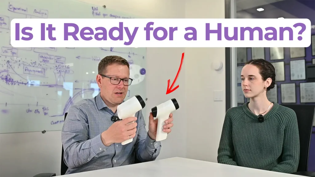
Ariana and Mark walk through what separates a clinical prototype from a proof-of-concept build, what determines how much testing and documentation you actually need, and where the regulatory line between significant risk and non-significant risk falls.
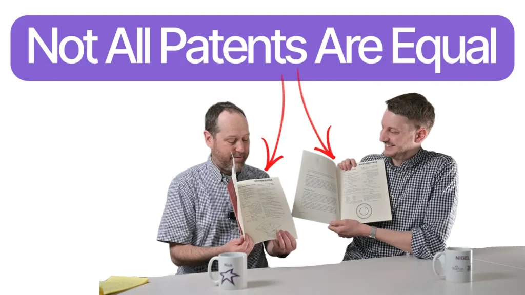
In this episode of Bio Break, Nick walks through both patent types after receiving two of his own in the mail, one of each, from the USPTO.

Scott Phillips sits down with Mickey Urdea to examine what actually distinguishes companies that reach commercial outcomes from those that do not.
Nigel Syrotuck breaks down the realistic medical device V&V cost and schedule for terminally sterilized devices, picking up after design freeze and walking through each major phase of the process.