Tips for Chassis Wiring in Medical Device Prototypes
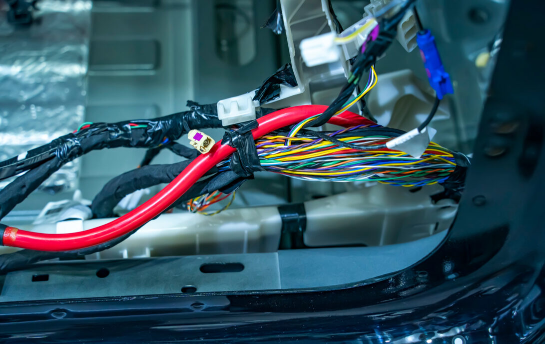
I routinely engage in the development of prototypes medical devices, which often demand careful attention to internal wiring and cable routing. These prototypes typically incorporate at least one printed circuit board (PCB) installed within a plastic or metal enclosure, featuring numerous connections to external components through various connectors. One often overlooked aspect is chassis wiring in medical device prototypes, which can become surprisingly complex if not addressed early. It is common to underestimate the intricacies of internal cabling and to defer its consideration until the latter stages of the project. Experience has demonstrated that this can lead to unnecessarily intricate and confusing cable arrangements.
The following recommendations outline strategies to mitigate these challenges. For ease of reading, this blog is broken down into design and assembly tips.
Design Tips
Careful Planning
During the design phase of a prototype, it is essential to thoroughly contemplate the assembly process. This includes determining the location of connectors on the PCBs, understanding their intended connections, and mapping the required pathways. Such planning enables the optimization of connector placement to facilitate short, orderly cable runs. Furthermore, it is critical to think of how much space is required to plug/unplug connectors/cables, especially if a tool is required!
Design to prevent cross plugging
In devices of all shapes and sizes, it is common to have several cable assemblies with a similar number of conductors. For simplicity’s sake, it can be tempting to re-use the same connector. However, this can lead to damaging circuitry, or lengthy debugging sessions.
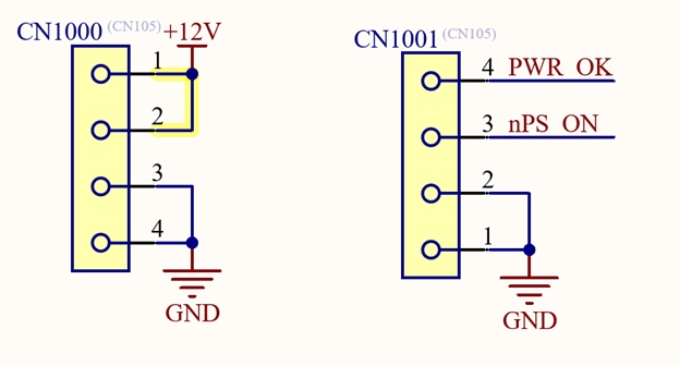
If I was intending to plug in CN1000, but accidentally plugged it into CN1001, it would short 12V directly to ground! To prevent this, I avoid reusing the same connector for different purposes, or to design the system to minimize the risk of damage in the event of accidental cross-plugging.
In the above example, this could be done by choosing a different connector for either CN1000 or CN1001. Moreover, incorporating easily readable silkscreen markings on the PCB can assist in identifying appropriate cable connections, which is particularly beneficial in larger devices featuring multiple point-to-point cable runs and distributed systems.
Cable consolidation and umbilicals
In instances where multiple cables converge or diverge from a similar termination point, there is an opportunity to consolidate them into a single umbilical cable connected to a PCB that distributes the signals appropriately. In some devices, this can lead to excessively bulky cables, which is not ideal. In these instances, it can be beneficial to utilize serializer integrated circuit (ICs) or multiplexers to cleverly reduce the total number of conductors. This has its downsides and should be carefully thought out before implementing. Additionally, it is advantageous to provide tie-down points, such as P-clips along the cable runs to maintain an organized and tidy wiring layout.
Assembly Tips
Crimping
In my experience, almost all post-assembly challenges with cable assemblies relate to poor crimping. This can be due to the wrong crimper being used or a lack of familiarity/experience in doing the crimping. If you are making the cables yourself, I strongly recommend at least one practice crimp on a spare wire or two, until you are satisfied with the results.
Insulation and wire gauges
When designing and assembling a cable, I strongly recommend using highly flexible insulation and carefully selecting wire gauges. Poorly selected insulation or overly thick wire can make managing conductors feel like a fight. Sometimes, in the case of high power, co/tri-axial, or RF cables, this is unavoidable but can be made easier with careful selection of the cable. If you have the time/budget, I always recommend ordering a sample of a candidate wire to determine if it meets all your needs.
Color coding
It can be tempting from an aesthetics perspective to use identical wiring for each pin in a connector, however this can make troubleshooting a nightmare. Using a color-coded, multi-conductor cable like the following can help make identifying misconnected conductors almost trivial.
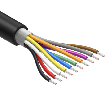
Furthermore, always use the same color wire for the same function. With the above cable, it may be possible to choose black as ground, red as power, and use the other conductors for data or other signals. If you need to hook-up an oscilloscope, multimeter or logic analyzer to a cable like this, you will know where to expect a particular kind of signal without needing to open a cable drawing or PCB schematic.
Labelling
Finally, heat-shrink labels, available for various handheld label makers, are highly advisable. These labels are invaluable in diagnosing wiring harness issues, particularly when conducting continuity tests across long multi-conductor cables. The labels benefit both the cable assembler and the final device assembler, as they help to minimize the risk of cross-plugging and reduce assembly confusion. At a bare minimum, I would suggest labelling both sides of a cable with their intended connection point, as well as the drawing number and revision. Other information, like individual conductor labels can be helpful, but too many labels can make cable ends stiff or immobile, which is not ideal.
Summary
I hope the recommendations and strategies in this article help mitigate some of the complexity associated with internal cabling for printed circuit boards in medical devices. I would enjoy hearing additional tips from readers.
Mike Ganzert is an Electronics Engineer at Starfish Medical. He received his Bachelor’s of Applied Science in Electrical Engineering from UBC Okanagan in 2021, with a focus in medical devices.
Images: StarFish Medical
Learn more about StarFish Medical.
Latest Resources

Nigel Syrotuck breaks down REACH SVHC compliance for teams working with material suppliers and compliance questionnaires.

We examine when computational modelling and simulation, or CM&S, genuinely supports medical device simulation strategy and when it becomes a costly detour.
Many teams still underuse CM&S, often bringing it late in device validation, when key decisions have already been made. That approach leaves much of the value of CM&S untapped.

This article traces the Pennes bioheat equation from its 1948 origins to modern multiscale approaches, explaining how engineers select the right level of modelling complexity across device categories.