
Pros and cons of two popular Ultrasound signal processing techniques
TL;DR
Two demodulation techniques dominate ultrasound signal processing, trading computational cost against image quality:
- Quadrature (IQ) detection is simple and hardware-friendly, but blurs image detail: By mixing in-phase and quadrature-phase sinusoids with the input signal, IQ detection reduces out-of-band noise and enables lower digitizing rates, but requires substantial low-pass filtering that softens the resulting image.
- The Hilbert transform produces sharper images at a higher computational cost: By shifting the input signal 90 degrees in phase and combining it with the original, this method estimates pulse energy more accurately and reduces ripple artifacts, though it demands more processing power to maintain decent frame rates.
- Both techniques remain in active use, chosen based on system tradeoffs: As computational power has increased, the Hilbert transform has become more practical, but IQ detection’s simplicity and cost advantages keep it relevant for modern diagnostic ultrasound systems.
Prior to constructing ultrasound images out of raw radio-frequency (RF) data, the transducer pulse frequency must be removed from the data to prevent ripple artifacts in the image. There are a number of methods of demodulation in ultrasound although two ultrasound signal processing techniques are used predominately nowadays.
The ultrasonic pulse consists of a series of pressure waves that radiates outward from a transducer. These waves propagate through the tissue scattering and reflecting off of variations in tissue density and elasticity. Some of this energy returns to the transducer, and is recorded as a short burst of oscillations, similar to the short burst of waves that hit a beach after a large ship has passed. Even if there is a sharply defined feature in the tissue – such as a bone – it will be recorded as a group of ripples in the image unless some preprocessing is performed first. Ideally, preprocessing will magically identify the centre of the group while removing any ripples.
This process is analogous to the demodulation of radio signals. It has the exact same intent, to remove the carrier signal and reconstruct the signal envelope. For this reason the process is often called “demodulation” or “detection”. Though coined during the development of radio technology, they sound intuitively correct for ultrasound as well.

The first ultrasound signal processing technique is quadrature detection, or IQ as it’s sometimes called. This method mixes (essentially multiplies) an in-phase and quadrature-phase sinusoid with the input signal, causing signal content of that frequency to be accentuated and all other content to be reduced. This method is relatively simple to implement in hardware or software.
It also reduces the effects of out-of-band noise in the signal. This can be a drawback, however, as it’s often advantageous for the emitted pulse to span a range of frequencies. If IQ detection is carried out in hardware, a reduction in digitizing rate can be considered, thereby enabling further cost reduction. IQ demodulation is typically performed as a first step for Doppler measurements.
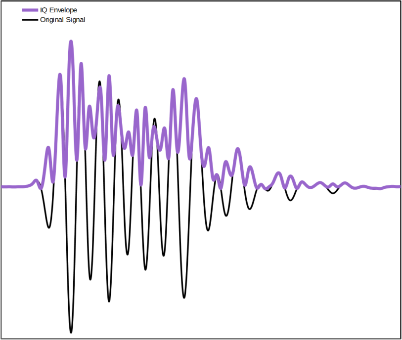
The raw signal after IQ detection can still be quite ripply at twice the carrier frequency, requiring a reasonable amount of low-pass filtering before the image is constructed. This results in some blurring. The first graph at the top of this blog shows a typical ultrasound echo signal and its corresponding envelope estimated using IQ detection. Note the double-frequency ripple.

The second ultrasound signal processing technique employs the Hilbert transform. It gives good results and is becoming more widely used with the advent of higher sample rates and higher digital processing capabilities. This somewhat esoteric mathematical function has the interesting property that it shifts the input signal by 90 degrees in phase, regardless of the signal frequency. This essentially shifts the peaks of the ripples in the RF data halfway in time towards the troughs. This modified signal and the original one can be combined, so that one fills in the ripples of the other, thereby estimating the envelope magnitude. The result is a very good approximation of the pulse energy, reducing the ripple image artifacts while maximizing image detail. . The second graph shows the same signal but with its Hilbert Transform superimposed as well as the estimated envelope.
Kenneth MacCallum, PEng, is a former Principal Engineering Physicist at Starfish Medical. He worked on Medical Device Development for a variety of areas including ultrasound applications.
Images: StarFish Medical
Related Resources

Nigel Syrotuck breaks down the realistic medical device V&V cost and schedule for terminally sterilized devices, picking up after design freeze and walking through each major phase of the process.

Accelerated aging in medical devices is a testing method used to estimate how a product will perform over time by exposing it to elevated conditions, most often heat. In simple terms, it is a way to simulate months or years of aging in a much shorter timeframe.

Medical device cleaning is more complex than it seems. In this Bio Break episode, Nick and Nigel unpack what really goes into cleaning medical devices and why it cannot be treated like a simple wipe-down process.
This blog reviews the main families of optical detectors and the major technologies in those families.
Explore Our Services

Our multidisciplinary teams have all the in-house capabilities to transform your medical device from concept to final product.

Medical device design and development with a commercial launch focus. See how we support clinical trials and facilitate seamless tech transfers.

We help you navigate complex regulatory landscapes to achieve commercial success. Explore our integrated approach to quality and regulatory services.