Medical Device Vibration Analysis and Testing Reduce Risk
The effect of vibration on medical devices can be understood through a combination of vibration analysis and testing. This blog discusses the medical devices most susceptible to vibration, basic theory and methods of vibration analysis, and the benefits of using modal analysis in the development of medical devices.
Modal analysis, the most fundamental portion of vibration assessment, can inform design decisions for critical component placement and overall device implementation due to the mode shapes and natural frequencies it quantifies.
Vibratory testing (including quantified transportation and environmental conditions) is mandated by IEC 60601-1-11 or equivalent standards for certain devices. These standards should be consulted when planning vibrations analysis to ensure the full range of conditions are represented ahead of the tests. Leading with an effective analysis of vibrations derisks product architectures and a clear path forward for development.
Which medical devices are most susceptible?
Vibrations analysis is best used when developing sensitive medical devices. Though vibrations should be considered a technical and safety risk in all devices, the most susceptible medical technologies include:
- Surgical Robotics
- MRI
- Ultrasound
- Microscopes
- Ventilators and Respirators
- Laboratory Analyzers
- Electrocardiography (ECG) and Electroencephalography (EEG)
- Laser Systems
- Implantable Devices
- Infusion Pumps
Many critical aspects of these systems are affected by vibrations including positional accuracy and image quality. Vibration can damage and disrupt mechanisms, introduce errors into quantitative diagnosis, misalign lasers, and impact drug infusion delivery. Understanding the influence of vibration to a sensitive system is paramount to patient safety and treatment, and to the effectiveness of medical device diagnosis.
Background theory
Many real-world systems can be approximated by one or several spring-mass-damped systems, where each portion contributes to vibratory effects. Figure 1 shows a single spring-mass-damped system in its most fundamental form.
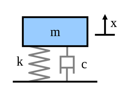
(source: Wikipedia)
From this, the following equation describes the distributions of each reaction force experienced by the system when a sinusoidal input force F(t) is applied (source: Lifetime Reliability Solutions):

Consider these inputs – mass, damping factor, and spring constant – and how they affect a system. If the same force is applied to a system with a small mass and larger mass, the acceleration will be lower for the system with the larger mass. Similarly, the same force on a system with a higher spring constant will have a smaller displacement.
Though a simplified theoretical model helps conceptualize contributing factors, in the real world, analyzed systems are almost always more complex. Being more complex, other factors come into play such as geometric transformations from natural frequencies, highlighting the risk of resonance amongst those natural frequencies. This is where Modal Analysis shines.
Modal Analysis – Natural Frequencies
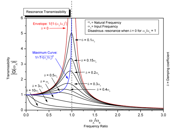
As a linear analysis, modal analysis takes a system through a range of frequencies and identifies the inherent natural frequencies. This only includes the mass and elastic portions of material properties ( and from above) and excludes any system damping. Natural frequencies are the points at which a system will oscillate in the absence of a disturbance, and if forced at these frequencies, will resonate (see Figure 2).
(source: Wikipedia)
Figure 2 – Resonance Effect on Input Frequencies with Damping Coefficients (source: Wikipedia)
Resonance with forced inputs causes a local maximum to occur, where the system will oscillate at a higher amplitude than non-resonant frequencies. This impacts design in many ways, such as causing worst-case displacements and accelerations. This impacts design by affecting:
- Material fatigue life
- System stability
- Subsystem risk of damage
- Overall device performance
If vibration is a critical design aspect, stakeholders should carefully consider the natural frequencies early in design when the system architecture is first drafted and make any needed adjustments. It should also be considered later in development, when subsystems and interfaces are being refined.
Modal Analysis – Mode Shapes
At a given natural frequency, the system will have a particular shape that scales with input power. This is called a mode shape and is fundamental to understanding where waveforms are expressed geometrically, especially the vibratory wave peaks and nodes. Complex systems have many mode shapes across a high range of frequencies but bounding them into a frequency range allows for efficient analysis.
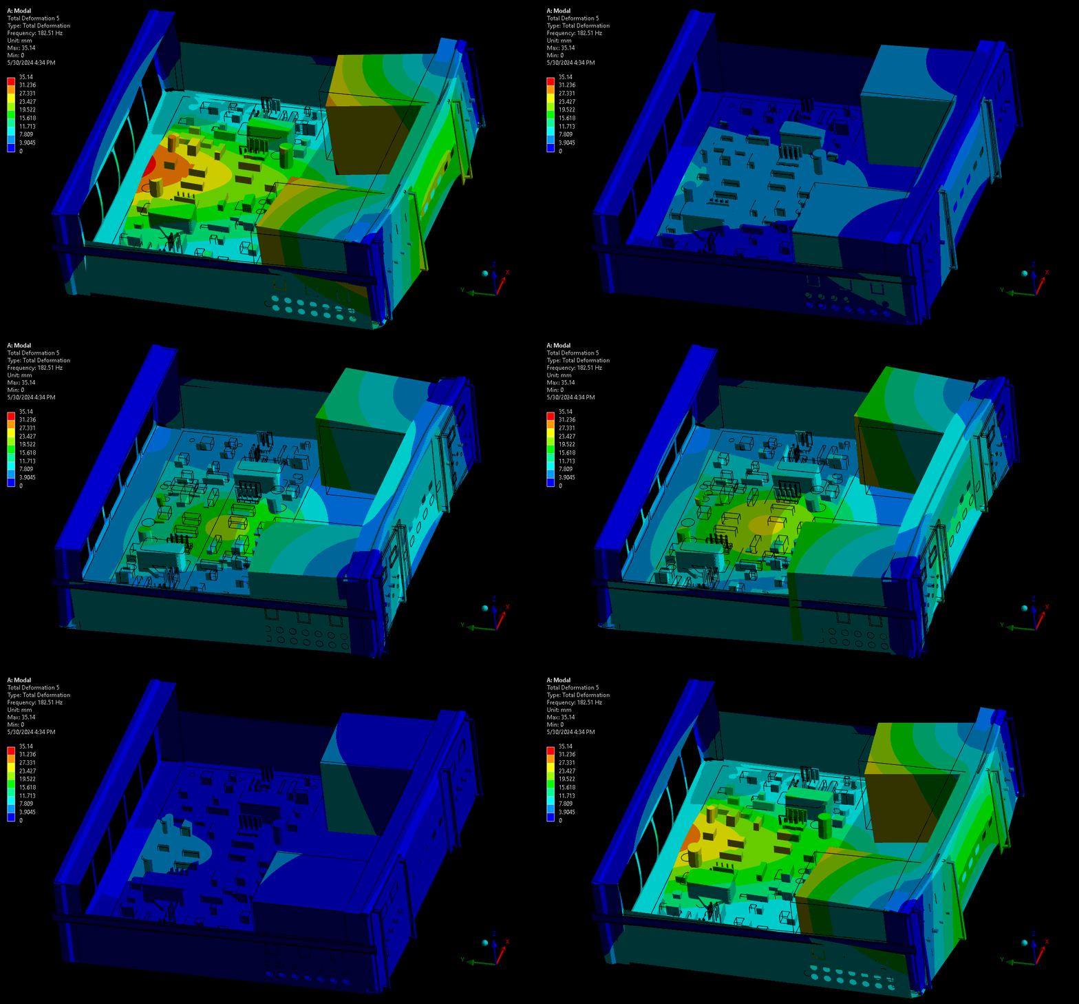
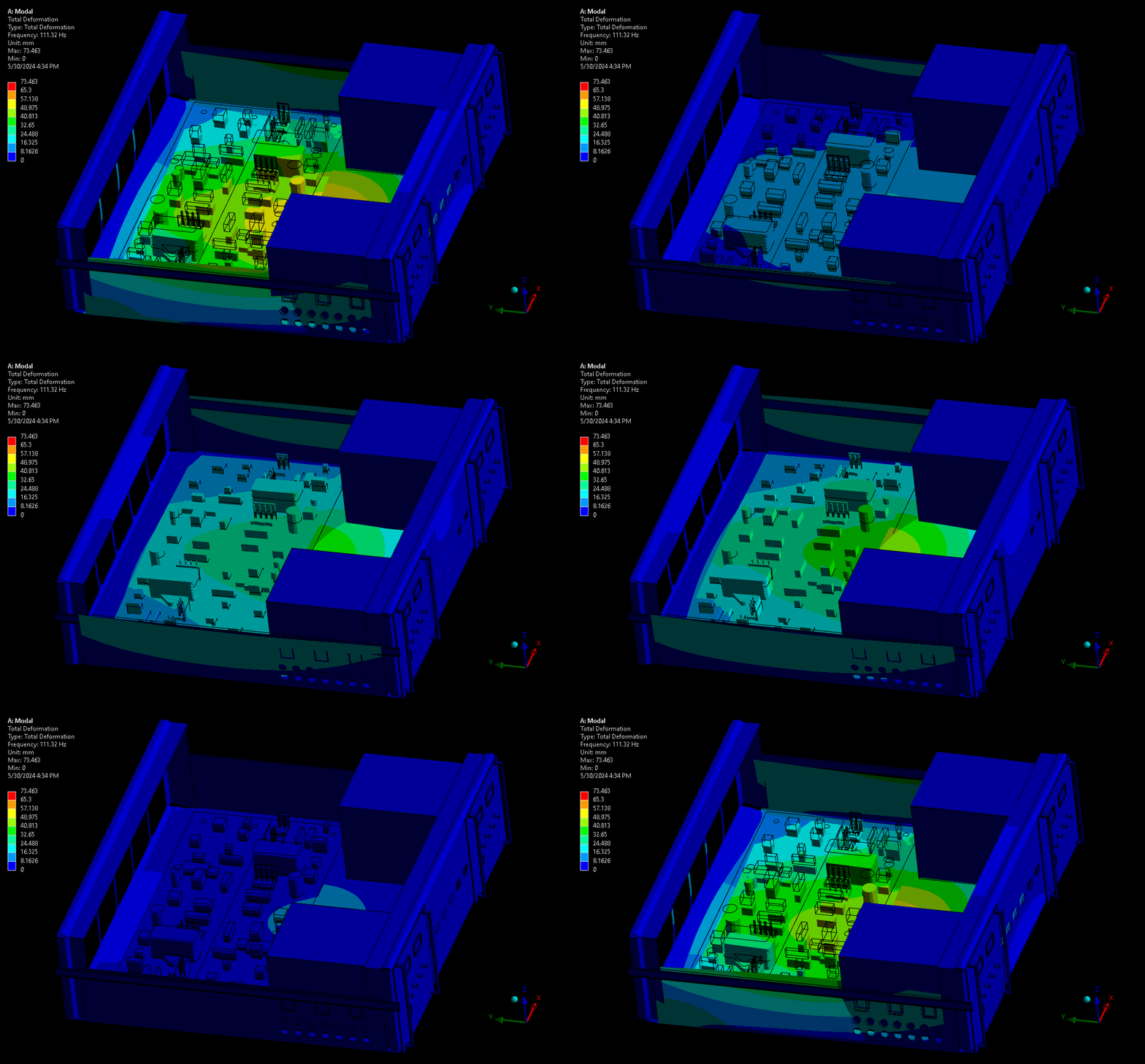
For assessing mechanical robustness, lower frequencies typically have higher power levels and larger amplitude wave forms and are therefore the highest concern. Take for example a complex device with sensitive electronics or optics. Ideally, these critical components are kept away from areas of high amplitude and acceleration – the results from a mode shape simulation shows designers where these locations are. Some example mode shapes are shown in Figure 3 and Figure 4, simulated via a computational model set up in our Ansys software. Note that the wireframe is the undeformed model, and the gradient-coloured model is the scaled mode shape throughout its sinusoidal waveform.
(source: StarFish Medical)
The fundamental frequency is the first in the series of periodic waveforms and has the simplest shape and generally the highest peak for the main geometry in a system. In complex systems it’s not always the lowest frequency, as there may be internal systems expressing their fundamental frequencies at lower frequencies than the main geometry.
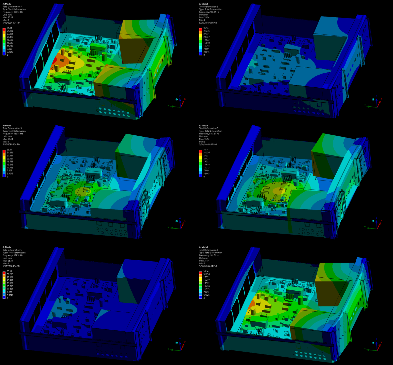
(source: StarFish Medical)
The higher modes provide more complex waveforms and geometry transformations at resonance, though with lower peaks than lower periodic modes (given the same input vibration power). As shown, this can cause more complex deformations on critical components like the PCBA and risk damaging the board, its traces, or its critical subcomponents.
As noted previously, modal analysis shows only a scaled shape at given frequencies. To quantify the risk in situ, it’s critical to gather vibrations data (physical or representative) from operating conditions and deployment environments. Stress analysis can follow by applying vibration power levels (Power Spectral Density inputs). A statistically meaningful method (e.g., random vibrations analysis) can then make the analysis relevant to system operating conditions and environments, preceding physical testing of prototypes/devices and preventing errant effects or damage to physical systems.
Conclusions
Vibrations are critical for many common medical device technologies, and applicable to all required medical device testing for target regulatory markets. Modal analysis can inform design decisions for critical component placement and overall device implementation. This leads to derisked product architectures and higher confidence for stakeholders in the development of medical devices.
Nathan Müller is a StarFish Medical Mechanical Engineer – Analysis and Design. His focus is in simulation engineering using computational modelling. As part of a design and development team, he frequently lead the development of mechanical design and device integration across disciplines, including targeted optimization and derisking activities through computational modelling and simulation (CM&S).
Images: StarFish Medical
Vibration testing is important for safety risks and for business risks Learn the XYZs of Vibration basics.