eGuide to Microfluidics Device Development
TL;DR
Bringing a microfluidic device from bench to market is one of medtech’s more demanding development challenges:
- Material selection, design simplicity, and parts sourcing strategy must all be resolved early. Decisions made at the proof-of-concept stage have outsized consequences on manufacturing yield, cost, and regulatory readiness downstream.
- Production yield for microfluidic devices can be as low as 50%, making a structured assembly workflow, clear quality control criteria, and tolerance management non-negotiable from the outset, not afterthoughts.
- Regulatory strategy must be considered during development, not after it. The intended use of the device determines the pathway, and that pathway shapes how the device is designed and tested.
This paper offers insights and case studies in designing and producing a reliable microfluidic device, then taking it through clinical testing to market. It highlights steps for testing device performance (part of regulatory compliance) and setting suitable acceptance criteria for successful market introduction.
Despite the compelling advantages of microfluidics, most commercial products are still in the developmental stage.
Commercialization challenges include integration into existing laboratory processes, developing appropriate assembly processes for micro features, and producing at scale within required tolerances and reliability.
Finished microfluidic devices may appear simple but designing and producing them requires an interdisciplinary team of engineers, scientists, medical practitioners.
Product development teams often include members with expertise in assay development, device design and modeling fluidics, materials, optics, and sensors.
Producing microfluidic products reliably at scale can be challenging. Microfluidic devices must be manufactured in a highly repeatable process at a high yield (particularly in medical applications).
10 considerations to ensure microfluidic device manufacturability
Microfluidic devices are versatile platforms for the variety of applications. Once the requirements of the intended application are identified, the product development process starts. Several factors must be considered to ensure that a reliable manufacturing process is developed [7]. The following are the key considerations.
1. Choose suitable component materials
Materials used in microfluidic device development are crucial to the product’s success. A recent report showed that most devices currently available in the academic and research sector are developed using polydimethylsiloxane (PDMS), glass, silicone, polymers, paper, and hydrogels. The choice of material will largely determine the best fabrication technique for an intended application. In all cases, it is crucial to determine the optimum material based on the manufacturability of the concept design. This will depend on the complexity of the fabrication of critical components, existing manufacturing tools capabilities, cost of the jigs and fixtures, and the overall product cost [6]. Here, we review the materials commonly used for microfluidic device manufacturing.
a. PDMS is the most widely used material, allowing rapid and effortless microfluidic chip fabrication. This polymer gained favor in the academic and research community due to its compatibility with rapid prototyping ability, easy fabrication, and affordability. PDMS is optically transparent, elastic, non-toxic, chemically inert, low-cost, and gas permeable. Fabricating a PDMS microfluidic device requires little equipment and operator training. These properties make it very attractive for many applications such as lab–on–a–chip, droplet generation, and cell or tissue culture.
b. Glass is the most desirable material for microfluidics because of its surface stability, thermal conductivity, solvent compatibility, outstanding surface roughness, superior optical transparency, and high-pressure resistance. Moreover, it is biocompatible, chemically inert, and hydrophilic. Glass is the first choice for many applications involving analysis with elevated temperatures and organic solvents. On the
other hand, microfluidic chips made of glass are expensive and difficult to manufacture.
c. Silicon is an excellent material for microfluidic devices, requiring high precision and features with tight tolerances. It has good surface stability, chemical compatibility, electrical conductivity, and the ability to integrate sensors and electronics within the device. However, silicon is not frequently used due to its opaque nature and the high cost of production as it requires the use of semiconductor microfabrication facilities.
“In selecting the appropriate materials, it is first essential to understand the intended application of the device along with understanding the chemical and rheological properties of the fluids and the relationship between surface roughness and the devices’ performance.”
d. Polymers (other than PDMS) are the third most used material in manufacturing microfluidic devices due to the low cost of production, several manufacturing processes options, and the availability of micro-macro interface parts. Using common polymers, the cost per device can be less than a dollar per unit, depending on volume. There are several types of polymers used in the fabrication of microfluidic devices. Properties vary; however, polymers selected are generally biocompatible and optically transparent. Polymers can be categorized into thermosets and thermoplastics.
• Thermosets are polymers that form permanent chemical crosslinks during the curing process. They are optically transparent, inexpensive, easy, and fast to fabricate. They do not melt, dissolve, or swell significantly in most solvents and are highly resistant to creep. Thermosets are not generally highly permeable to gases. One of the most commonly used classes of thermosets in microfluidics is ThermoPlastic Elastomer (TPE).
• Thermoplastics are an excellent alternative for microfluidic devices. These polymers can be shaped, softened, and melted when heated. The intermolecular bonds in a solid thermoplastic polymer can temporarily break when applying heat, pressure or an appropriate solvent. Thermoplastic polymers include polyether ether ketone (PEEK), polystyrene (PS), polyethylene terephthalate (PET), polyvinyl chloride (PVC), polymethylmethacrylate (PMMA), cyclic olefin copolymer (COC), polycarbonate (PC) and polyetherimide (PEI).
e. Paper is used in paper-based microfluidic devices due to its ready availability and low cost. Paper-based devices are cheap, easy to manufacture, biodegradable, and easy to stock. They are also compatible with biological samples and can be chemically treated to bond with molecules or proteins. Paper devices are the basis of lateral flow diagnostic devices wherein fluid flows along a pre-determined wicking channel and reacts to the reagents pre-positioned along the path. However, paper-based microfluidic device are not well suited to complex mixing, incubation, and extraction processes.
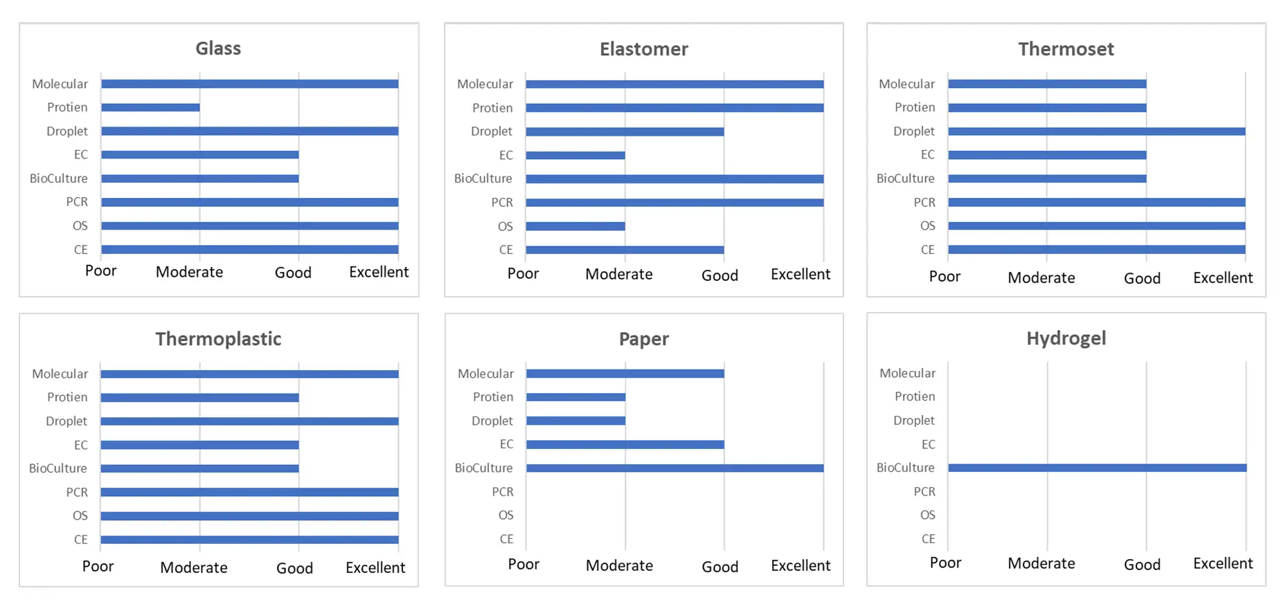
Materials for microfluidic device fabrication.[2],[8],[9]
2. Have a high-level overview of the device design, technical risks, and system architecture based on vetted requirements
It is essential that the device requirements are clearly communicated and understood. These requirements must be documented in as much detail as possible and ideally vetted by stakeholders. They will enable the design and development team to align expectations and help determine and synchronize tasks and processes.
“Given the product intent, how do we achieve the design goal and convert it into actionable tasks?”
Identification of requirements can start from a high-level goal or intent to miniaturize and automate existing assays for intended applications, including complex mechanical components and detailed assay processes. Understanding these would increase the chances of success during the early phases of development. The design and process requirements are the foundation of the device development efforts and implementation. In any microfluidic platform, there are at least three components, (a) assay – this is the fluidic protocol to be translated to the microfluidic format, (b) the device or cartridge is the component that contains the microfluidic network and (c) the instrument or reader for fluid flow actuation and detection of selected outputs. Understanding the interplay of requirements with these components is crucial. Lack of clarity and rigorous vetting can lead to many unnecessary challenges. The best practice is to triage the requirements by ranking the importance towards the overall success of the device.
Assay requirements include understanding the reagents and their properties, such as viscosity, chemical compatibility, and required volume. Knowing how the reagents are introduced in the microfluidic device is also essential. For example, are they preloaded into the device, or will a blister package be used instead? Which reagents will be stored within the cartridge, and which will be manually introduced in the process? The properties of reagents are also crucial to determine how the fluid will move in the reservoir and channels.
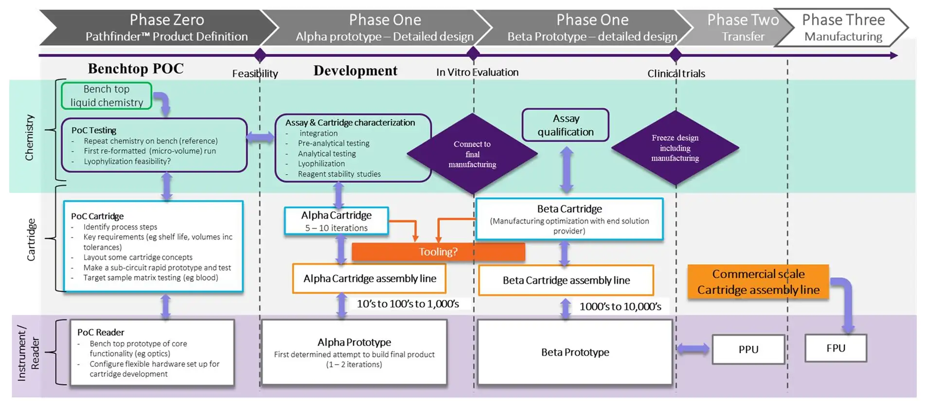
Microfluidic device development stages.
The type and materials of the reservoir in the device will affect the storage shelf-life of the reagent, its effectiveness, and its interactions with other reagents. In some microfluidic devices, freeze-dried reagents are preferred to avoid liquid handling, complicating the design. It is recommended to create a detailed list of features and processes involved in the assay protocol, for example, the number of reagents in the protocol, volumes, fluidic properties, volatility, material compatibility, biocompatibility, and composition (i.e., beads, cells).
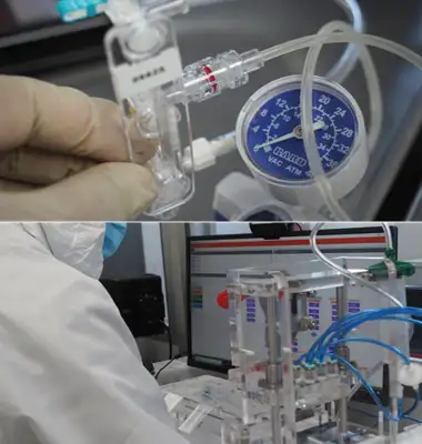
Fluid flow actuation methods can include positive pressure, vacuum, electrostatic, ultrasonic, capillary action, or pumps such as diaphragm, piston, film, or even peristaltic. Actuation timing and flow rates must be well-defined. Since the microfluidic process is the miniaturized version of the laboratory workflow, the proper timing of each process at a pre-determined volume is important. Some assays include a targeted assay protocol timing per unit operation, such as the introduction of the sample, mixing, metering, incubation, pre-filtering, separation, sorting, binding, and washing steps. A list all the unit operations with corresponding reagents, volumes, processes, timing, flow rates, and other protocol-specific parameters, will help a lot. Additional requirements, such as the type of materials to be used, surface treatment if needed, manufacturing, and cost consideration, must be included on the list. These design requirements will guide the engineers in developing a device concept that efficiently implements the assay protocol.
Once the requirements have been determined and fully vetted, design concept options can be developed and evaluated to decide the best design path to pursue. The initial design could be a modification of the existing devices, integration of off-the-shelf (OTS) components, or a totally custom solution. If the design requires OTS components, their specifications must be reviewed, considering their compatibility with other cartridge materials and the feasibility of their integration. OTS components include pumps, valves, filters, tubes, ports, interfaces, and the like. It is generally advisable to select several OTS options and review the advantages and disadvantages of each, including whether to use OTS components or custom-build the component. In many cases, OTS components can drive the overall dimensions and performance of the cartridge. Be very careful with this integration.
Another key design concept element is the unit operations to be performed inside the cartridge. These include sample ingress and egress, reagent storage, mixing, metering, material filtration, analyte detection, and more. Sample ingress and egress are part of the user interface design. The introduction and collection of the sample guides the handling of the device and the overall form factor. Medical practitioners will find poorly designed cartridges challenging to use or, in some cases, even pose a hazard.
There are four major elements in device conceptualization.
• Reagent mixing in a microfluidic cartridge is a standard unit operation, including mixing biological samples with other reagents (i.e., lysing, tagging, reconstituting, diluting, and incorporating). Mixing inside the cartridge can be done in several ways: by shaking, magnetic mixing, use of vortex, application of acoustic pressure, material transfer, or other mixing techniques.
• Sample metering is one of the most challenging features to implement in a cartridge. Because microfluidic channels handle fluid at sub-microliter volumes, accuracy in metering fluids is of utmost importance. In assays that require precise measurement, metering is a huge challenge. Metering is typically classified as passive or active. Passive metering uses the pre-determined channel and reservoir volumes to dispense desired quantities of reagents. Active metering uses sensors to monitor the volumes dispensed actively.
• Material properties determine whether the material is compatible with the reagents used for the intended application. Several candidate cartridge polymers have been used in initial prototyping because of their temperature performance, bonding, stability, optical characteristics, and machinability properties. Manufacturability will also drive the ability of the yield and overall cost of the product.
• Analyte detection is particularly necessary for point-of-care devices and benchtop equipment. In some designs, optical lenses can be integrated into the cartridge to facilitate imaging or electrical data collection.
3. Sourcing and parts production plays an important role in device design
The availability, compatibility, and manufacturability of parts and components are crucial in building microfluidic devices. In the device design process, it is important to understand the parts and materials to be used in the initial proof of concept and, probably, change it in the scale-up stage when most of the technical risks have been identified and mitigated. It is important to understand the critical requirements of
the selected design to lay out the strategy for collecting and building the component parts. In many cases, the parts design and build are the most critical stages in implementing the integrated device design.
A common mistake in microfluidic device prototyping and scale-up is using the wrong fabricated parts for the proof-of-concept or functional prototype for testing. These parts may have excessive surface roughness or poor finish quality, which may impact the flow of fluids within the channel (e.g., for micromachined parts).
In the extreme case, channel blockage or clogging will render the device non-functional. For polymer materials, injection molding or hot embossing are preferred parts production techniques since they provide excellent micro features with excellent quality surface finishes.
Alternatively, rapid prototyping techniques such as 3D printing at high resolution (up to 2 µm), makes device prototyping faster and more accessible.
4. Decide on the use of off-the-shelf or custom-built components
Another aspect of microfluidics device development is the integration of OTS components or building custom components for the microfluidics platform. OTS component integration includes: the interface between micro and macro elements, alignment with instruments, sealing required for the actuators (i.e., pneumatic actuation), inlet and outlet interface for biological materials and the reagents, and the interface between the detection subsystems. All components for the integration must be characterized based on the specifications and tolerances. Once the integration is successfully achieved, it must be tested and evaluated with respect to the required specifications. At this stage, design iterations are expected, guided by testing to reduce the risk of excessive repetition.
Typical failure modes encountered in the device related to parts and their assembly are as follows.
• Missing critical parts or features.
• Too many parts, making the device too complex or costly to produce consistently.
• Incompatibility of the parts materials with assay reagents.
• Integration of OTS components to custom parts.
• Non-structured assembly process reducing production yield.
• Tolerance issues.
• Fabricated parts variabilities (repeatability).
• Alignment issues.
• Fastening and bonding challenges.
5. Determine the appropriate manufacturing methods for parts production and follow a structured assembly process
When the concept has been thoroughly vetted and reviewed for potential risks, it is necessary to initiate prototyping of the parts or the device to confirm utility of the design. There are various techniques to fabricate microfluidic devices. Depending on the design concept, this could be photolithography, soft lithography, thermoforming, or etching techniques. In determining the optimal method, it is important to consider the following: the appropriate material to be used, available equipment, critical dimensions and features, cost and time of manufacturing, assembly, and the interfaces required to operate the device.
In prototyping, different fabrication techniques may be suitable depending on the required volume and stage of development: (a) small volume – rapid prototyping to assess the basic assumptions, (b) mid-volume – alpha prototype for evaluating the product requirements and fine-tuning assumptions, and (c) large volume – scale-up for mass production and market introduction.
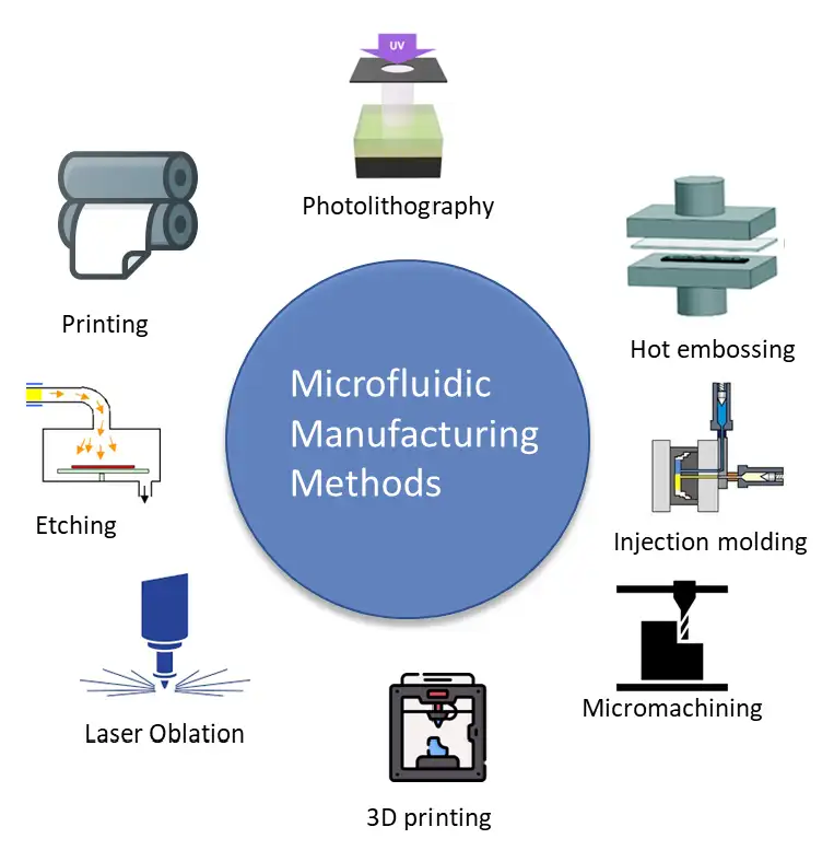
The following manufacturing methods are commonly used to produce microfluidic devices.[3],[4],[6],[8]
a. Photolithography is a prototyping technique wherein the features are created using light to produce geometric patterns, generally from a transparent mask onto a substrate using a photosensitive emulsion layer called photoresist. On the other hand, soft lithography uses a soft elastomer material (i.e., PDMS) to transfer patterns to a substrate material. This technique is simple and easy to use for prototyping high-resolution features at low cost.
b. Hot embossing is used to pattern thermoplastic materials against a master (stamp) by using pressure and heat. Thermoplastics can be remodeled when heated near the glass transition temperature (Tg). The stamp and the chosen polymer substrate are placed in a hydraulic press and heated above the glass transition temperature of the polymeric material to make it deformable. The master mold is pressed into the polymer substrate with precisely controlled force to emboss the plastic against the stamp, and the pattern of
the mold replicates on the substrate. A variant form of hot embossing is hot roll embossing. Hot roll embossing is the same, except that two rolls are employed to apply pressure. Hot roll embossing is generally employed for mass production since it may be easily employed in a high throughput process.
c. Injection molding is another thermoforming technique. This technique is a replicating process in which a material is heated to its melting temperature and injected under high pressure into a mold cavity. The polymer component is liquified by heating inside a barrel, then the liquid polymer is blended and quickly injected into a clear-cut mold cavity under high pressure. The micro-mold must be maintained at a temperature above the material’s melting point until the end of the filling process to ensure a complete mold fill. The material is cooled below its Tg and hardens, adopting the shape of the cavity. The finished part is then ejected. This process allows for a high throughput fabrication with a substantial production capacity. Parts produced using the process are repeatable and low cost.
d. Micro-machining is a very popular prototyping technique using CNC (Computer Numerical Control). The micromachining process involves the mechanical carving of substrate material. The smoothness of the micro-milled substrate depends on various parameters, including the spindle speed, depth of cut, feed rate, and operating environment. Micro-milling offers low-cost, flexible, fast fabrication or the ability to fabricate complicated structures. However, the minimum feature is dependent the bit size (i.e., 10-20um bit).
e. 3D printing has advanced significantly in the past several years for microfluidics development. Resolution down to 2 µm has made it possible to prototype small channels and parts that are difficult to produce using other fabrication techniques. The ability of the 3D printing technique is limited by the available printing materials, most of which are not optically transparent. Another limitation is the surface roughness and chemical compatibility of the printed materials. However, 3D printing is gaining popularity due to its ability to produce prototype parts without sophisticated and complex tooling.
f. Laser ablation and cutting is cutting-edge technology in fabricating microfluidic devices from glass and polymer. Microchannels in thermoplastic polymeric materials (including poly(methyl methacrylate), polystyrene, and cyclic olefin polymer) with surface roughness comparable to those obtained by standard prototyping techniques such as micro-milling can be produced using a femtosecond laser processing technology.
g. Etching is the process in which layers are selectively removed from a surface using chemicals. Etching is commonly used with silicon or glass substrates. There are two techniques used in etching: wet etching and dry etching. Wet etching is the removal of a material by using appropriate liquid chemicals or etchants. The substrate is covered by a photomask that protects the selected areas from the etchant. Briefly, material that is not protected by a mask is removed by the wet etchant. On the other hand, the dry etching process involves the removal of substrate material by plasmas or etchant gases. Dry etching is performed by ionizing a gas mixture inside a chamber to produce ions that react with the target substrate. Dry etching techniques are widely used to transfer patterns into a substrate with high precision. However, dry etching is more expensive than wet etching.
Advantages of different manufacturing methods.
| Manufacturing Methods | Pros | Cons | Recommendation |
|---|---|---|---|
| Lithography | Stable, reliable high resolution Excellent surface roughness | Complex fabrication High cost Requires special tools | Sensor integration High resolution features Master template |
| Hot emboss | Quick turn around High output High resolution and precision Low cost | High set-up cost Repeatability of build Uneven pressure distribution Limited material selection Not for complex designs | Rapid Prototype Use only for compatible reagents scale-up |
| Injection Mold | High output volume High-resolution and precision Low cost per unit at a high volume Excellent for scale-up production | High set-up cost Not for low-volume production | Scale-up production |
| Micromachining (CNC) | Quick turn around Acceptable resolution and precision Good for initial prototype Easy to use | Complex fabrication Low volume Low repeatability Acceptable surface roughness Features limited to bit size and type of materials | Rapid Prototype Proof of principle built |
| 3D printing | Quick turn around Acceptable resolution and precision (2 – 50um) Good for initial prototype Easy to use | Low volume Low repeatability Rough surface Features limited to resolution and type of materials | Rapid Prototype Proof of principle built |
| Laser Oblation | Quick turn around Acceptable resolution and precision (10 – 20um) Good for initial prototype | Low volume Low repeatability Features limited to resolution and type of materials High cost and time to build | Rapid Prototype Proof of principle built |
| Etching | Quick turn around Acceptable resolution and precision (10-20um) for glass and other materials | Low volume Low repeatability | Rapid Prototype Proof of principle built |
6. Importance of establishing an assembly workflow
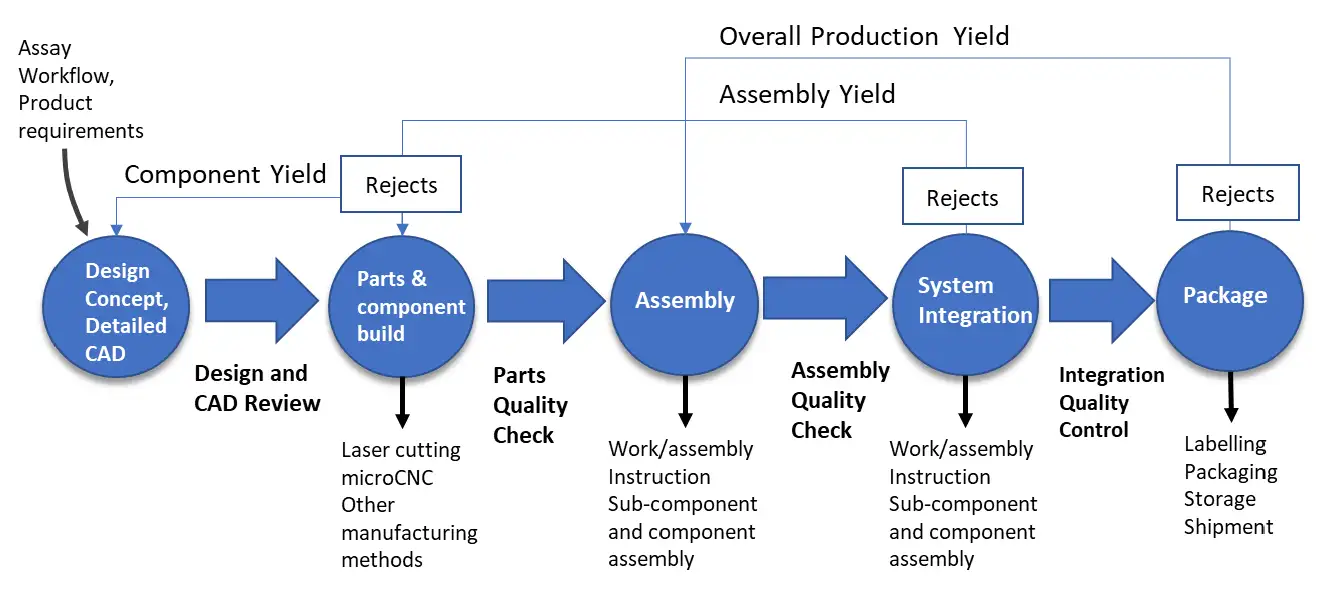
Quality control areas in the production of devices.
Developing an assembly workflow is a very important aspect of prototyping and scale-up manufacturing. There are four elements in establishing and structuring the assembly process.
a. Assembly workflow. During and after the conceptualization of the cartridge design, it is important to consider how it will be assembled. At low-volume production, assembly procedures may include staking of layers with adhesives or other bonding techniques. It is critical to understand the limitations of the assembly technique early on to streamline the process. Some steps in the microfluidic device assembly are parts preparation, cleaning and integrating OTS components, stacking, quality control testing, and packaging. There can be additional assembly steps depending on the number of parts, modules and complexity of the products.
b. Assembly jigs and fixtures. Assembly jigs and fixtures are critical elements during the conceptualization and detailed design of the device. The dimensional tolerances of the individual components will directly affect the tolerance stack-up of the multi-component device configurations. The proper jigs and fixtures are essential to assemble all the components for the build and to reduce build errors.
c. Quality control testing should consistently be implemented on the design of the device to ensure reliability and repeatability of performance. With jigs and fixtures, quality monitoring sensors can be integrated to facilitate qualification and inspection control for the dimensions, tolerances, orientation and fitness of the components during the assembly process.
d. Assembly trial run. A pilot run of the assembly workflow provides an opportunity to debug and troubleshoot potential pitfalls in the assembly process ahead of the production of units. It also provides a chance to make changes that increase assembly efficiency. During the trial run, time-motion data may be collected that will improve the assembly timing and identification of bottlenecks within the process.
Having a well-structured assembly process, may not be critical at the prototyping phase but it will be advantageous to follow a standard process that can be refined as the assembly process scales up to volume manufacturing. The assembly workflow requires documentation at different stages of the device life cycle, from production of parts to building the final product.
To ensure, reliability of the build, it is important to document the development and assembly process. It is worth mentioning that the assembly procedures can be changed from time to time as the product matures. There is no need to create an complex assembly line during the prototyping phase; instead, a sequence of steps on how the device is built using basic assembly jigs and fixtures will suffice at this phase of development.
Microfluidic devices are typically single use. Setting good quality control targets early in the prototyping phase helps ensure reliability and repeatability in prototype builds that increase yield in production. Five ways to monitor quality concerns associated with cartridge design are:
• Detailing quality inspection parameters. Providing detailed inspection features such as size, surface finish, cleanliness, and integration of OTS components helps facilitate the inspection
process. An initial inspection can be used to screen for critical features in quality control checks during cartridge production.
• Finding failure modes in assembly and component integration. Addressing assembly failure mode analysis early in the cartridge prototyping phase ensures the success of cartridge assembly. Some challenges that are encountered during assembly include misalignment of parts, leakage issues due to bonding, and improper integration of OTS components.
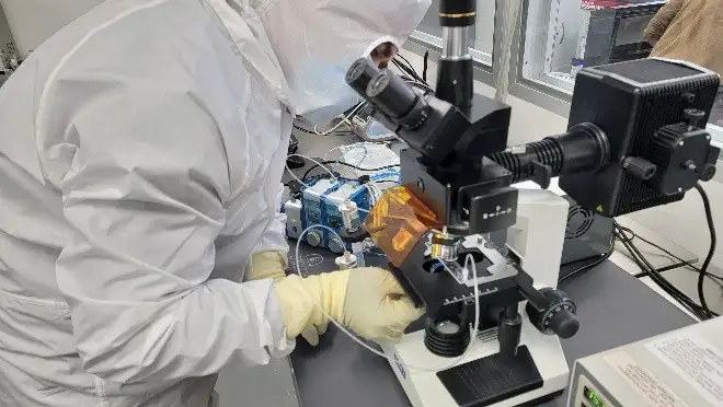
• Visual inspection of critical parts and channel profile. Critical features should be verified via a detailed inspection as part of the quality control process. Channel profiles should also be inspected with a profilometer to ensure surface roughness and channel depth are within specifications, as they affect fluid flow parameters in the cartridge.
• Pressure decay testing. Pressure decay testing can be used to set a benchmark for a successful seal of the microfluidic cartridge. It can be achieved by pressurizing the cartridge at a pre-determined level and using the observed decay rate as an indicator of an effective cartridge seal.
• Fluid flow testing. DI water or dyed dummy reagents are used during fluid flow testing to evaluate the cartridge’s fluid flow properties. Using dyed water facilitates visual observations of the tested cartridge and is very effective in assessing the mechanical performance of the cartridge.
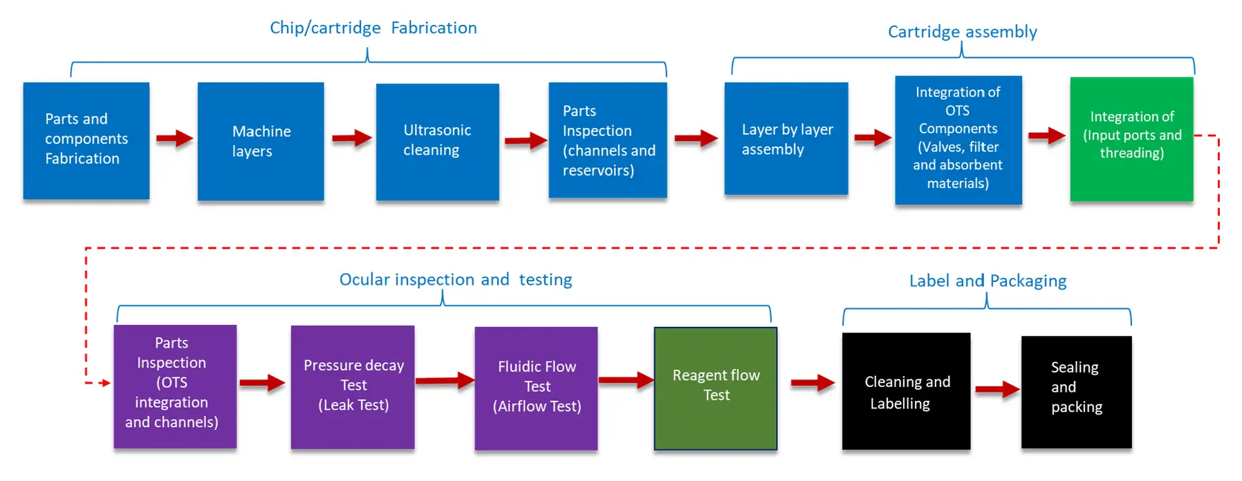
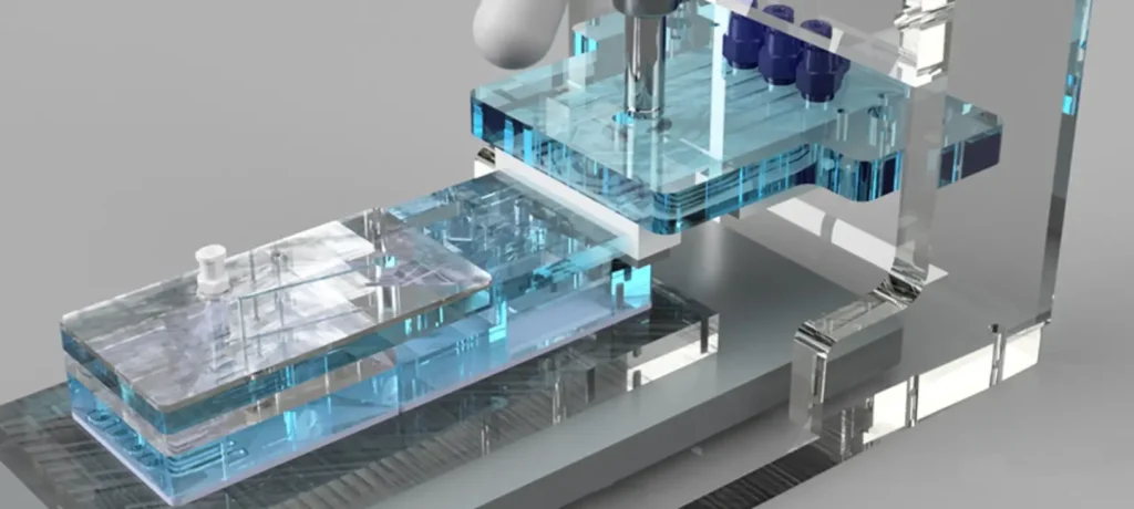
An example of a simple assembly workflow.
7. Systems Integration
A system approach to microfluidic device integration is crucial for understanding how the selected microfluidic parts and components will behave when integrated with other subsystems. Considering the overall system, which includes the microfluidic cartridge, the fluid delivery components, and the detection instrument will provide guidance on how each subsystem can be assembled, interfaced, and operated as an integrated system. The overall system may also include the workflow and fluidic processes implemented in the device and platform.
In some device designs, due to the complexity and cost of prototyping, workflow and process simulation are recommended to have a basic idea of the potential outcomes. Microfluidic device features such as channel geometry, the effect of heat transfer, material properties, applied pressure/flow, mixing and hydrodynamic effects could be simulated using known equations and models. There are several simulation and modeling software packages available that provide a comprehensive analysis of multiple factors that will guide our design and decisions thus reducing cost in prototype iterations and fabrication-test cycles.
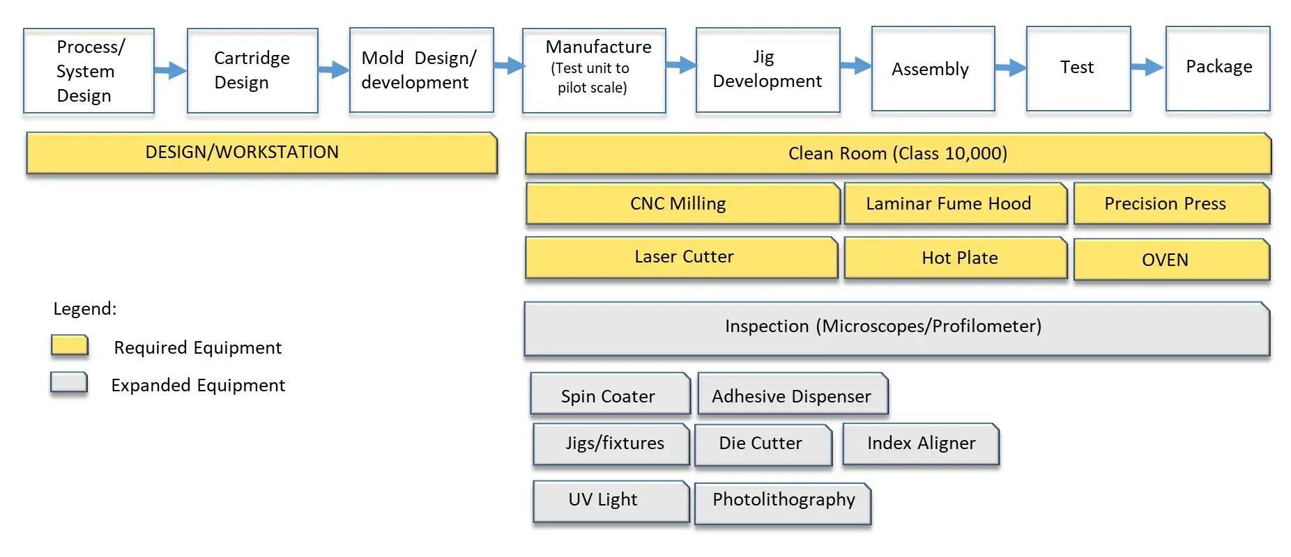
Microfluidic device production flowchart and basic facility requirements.
8. Cost assessment as an integral aspect of device development
Final product cost is always a key constraint in a device development process. The microfluidic device often must not exceed the price of an existing reference device available in the market. It boils down to the profitability of the product for the manufacturer and the affordability for the target users.
a. The number of parts or components required in the device.
b. The type of materials and fabrication method used.
c. The cost of raw materials, including OTS components.
d. The assembly process and its complexity.
e. The cost associated with the integration of subsystems.
f. The surface treatment processes.
g. Device performance and manufacturing yield.
These cost drivers should be minimized to reduce the overall build cost without sacrificing the quality and functionality of the device. In production volume scale-up, economies of scale will considerably reduce cost. In terms of determining the cost of goods sold (COGS), a reversed computation of potential selling price is used with respect to the different players within the supply chain. Here, the device production cost is kept to the minimum to beat the current price the end user is willing to pay.
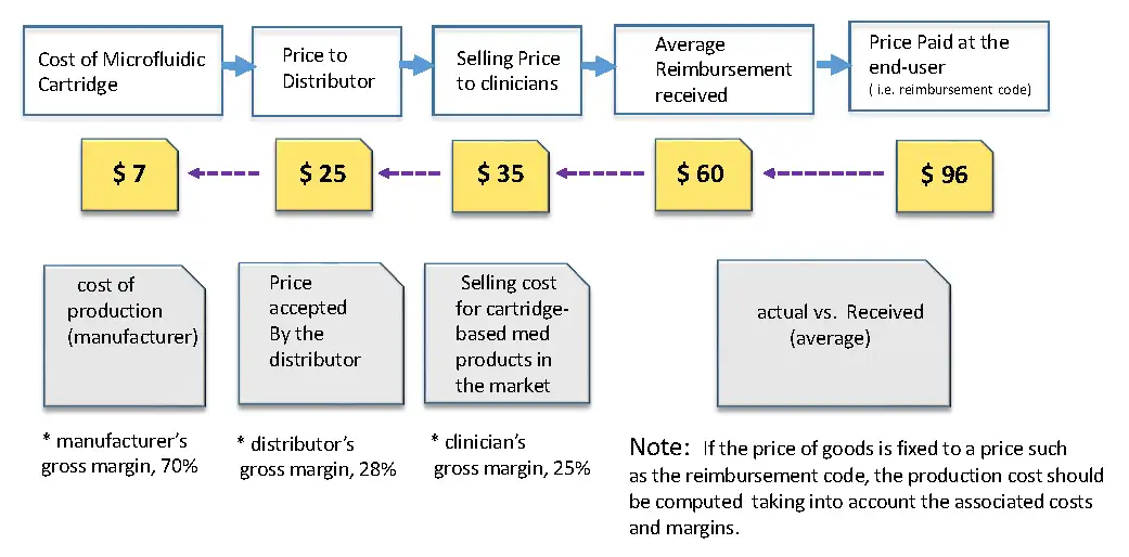
Cost estimation process for a microfluidic device.
9. Spend time conducting performance evaluation
In any product development, testing the assumptions, qualifying the fabricated and assembled product and the overall performance is a standard procedure to ensure the quality of the product. Testing requirements in every stage of development is necessary to ensure that every element is working according to the pre-set criteria. When and where in the process is the performance evaluation required? In theory, it is required in every processing step however, it depends on how critical such testing is at that processing stage.
The testing must have a detailed procedure and proper instrumentation must be in place. The testing could be implemented to check the part’s quality, specifications, and performance. It could also be at different checkpoints such as at (a) the assembly line for parts integration, (b) the mechanical and fluidic integration, and (c) the stage where the actual reagents and samples are added to the device
10. Consider the regulatory path for the final device
During the development of microfluidic devices, the regulatory strategy must be considered early on. The intended use of the device determines the possible regulatory pathways. It is crucial to have at least a high-level understanding of the regulatory processes, requirements, and timeframe of the possible submissions. Furthermore, informed regulatory guidance will serve as a baseline for how the device will be designed and used.
8 critical steps to device reliability
During microfluidic device fabrication and assembly, completed devices may pass quality control but fail during normal use. The ratio of functional units to produced units is called “overall yield”.
While it is desirable to achieve a production yield as close to 100% as possible, due to the typical complexity of microfeatures and assembly processes, yield can often be as low as 50%.
The main challenge is to increase yield by addressing root cause issues emanating from device design, parts production, assembly, and quality control procedures.
Microfluidic designers and engineers should explore different designs, parts production, and manufacturing techniques to increase the likelihood of successful builds, and increased production yield.
During initial design and fabrication, microfluidic devices are produced one at a time, manually. Therefore, the expected failure rate is high. As device development progresses and volume ramps up using automated systems, device yield will usually improve dramatically.
Microfluidic devices are fabricated via a variety of methodologies. A simple design could use a micro milling machine, a more complex design may employ a photolithography technique, and 3D printing is suitable for rapid prototyping.
Embossing and micromachining offer a more stable production output at small scale. However, for mass production, manufacturing methods such as roll-to-roll, injection molding or printed microfluidics are the preferred route. These manufacturing methods require huge investments linked to a large production volume commitment.
If your microfluidic design has not yet been prototyped at low volume and tested using a real sample, do not jump to mass manufacturing.
Several successful microfluidic designs and prototypes have been produced on a commercial scale and multiple vendors offer off-the-shelf microfluidic cartridges. Many of these service providers are located in Europe, Asia and North America.
It is very important to have a reliable and repeatable cartridge for use in analytical or pre-clinical testing stages of development that typically require several hundred or thousands of units. Considering the high cost of reagent and samples, make sure your cartridge is functional and can run the assay protocol from start to finish to avoid costly missteps.
“ It is important to have a list of critical features and parameters that targeted users believe will impact the result.”
Here are 8 critical steps to increase the reliability of your microfluidic device.
1. Check the design and fabricated parts for any missing parts or features
This is a design and/or an assembly challenge. When critical features are overlooked, the reliability of a device is compromised. As part of a standard examination procedure, critical parameters must be listed with sufficient details. It starts with the high-level assay workflow diagram including steps and processes mapped out. These should include input samples and output products and all the steps in-between.
This information is often not documented in detail and treated as common practice; however, it can affect the performance of an assay in a microfluidic format.
Several cartridge components are highly dependent on the mode of use. These components include channel dimensions, reagent and mixing reservoirs, metering, incubation, a fluid actuation mechanism, off-the-shelf components integration, and interfaces. To avoid missing critical features, it is best to (a) have a clear assay workflow with important requirements listed, (b) detailed list of reagents including material compatibility, storage requirements, and fluidic characteristics, (c) a list of all the parts including dimensions and off-the shelf components, (d) detailed step-by-step procedures, and (e) notes and comments from lab engineers or scientists who perform the assay protocol.
2. Be mindful of device design vs. intended function
At the initial fabrication build, it is possible that 75% of microfluidic devices produced will be non-functional. The possibility of failure is usually high if the design is very complex. While it is desirable to accommodate all the assay workflow requirements and features, the limited footprint of a microfluidic device may necessitate some design trade-offs. This requires an effective prioritizing of processes to be implemented in the cartridge. Often, additional features can be integrated into a companion instrument or carried out manually. As a rule, cartridge design simplicity is directly proportional to the build success rate.
A complex design can introduce many attractive features; however, each feature will introduce potential failure modes. Moreover, design complexity will also increase prototyping time, add raw materials, and increase assembly development time and cost.
Ultimately, a balance must be struck for cartridge performance (reliability), manufacturability (repeatability of build and yield) and the cost per unit cartridge. It is recommended to identify and rank the importance of each assay step, and then decide what should be included in the cartridge and make necessary adjustments to the protocol. Consider focusing on assay requirements that are critical to the assay protocol and product. In some successful cartridge designs, there are only 2-3 important features: a mixing mechanism, fluid metering and interrogation zones for analytes detection.
3. Selecting the right material is crucial
Material selection is very important in microfluidic device development. Selected material must be compatible with the assay. As a recommendation, consider the following: (a) check your stock material against the reagent(s) you will use in the assay (chemical and biocompatibility); (b) review optical properties for analyte(s) detection, (c) consider the fabrication method (micro-machining, embossing, injection molding, etc.), (d) evaluate bonding properties and adhesives and lastly, (e) outline an assembly workflow.
4. Limit the number of parts and off-the-shelf (OTS) components
To speed development of a cartridge, design and development processes are often abbreviated. One approach to save development time is to integrate off-the-shelf components and avoid the time-consuming effort of custom designing parts that are commercially available.
OTS parts include valves, connectors, plugs, filters, tubes adaptors, pumps, reagent packs, inserts and more. In general, it is best to keep the number of OTS components to a minimum. The more OTS components integrated in the cartridge the higher the chance of failure in the assembly and scale-up production. It is a good design practice to maintain OTS to essentials and explore creative ways to replace component function via cartridge design.
5. Be watchful of alignment and tolerancing
Failure to consider stack-up tolerance in a design is very likely a disaster in the making.
It is advisable to obtain a CAD drawing and specifications for the channels, reservoirs, mixers and OTS components (if any). Make a trial design layout and position the cartridge layers and other components using a guide pin. Decide on the fabrication method and adjust the tolerances accordingly. It is important to maintain the overall dimensions of the cartridge relative to the instrument reader interface.
6. Simplify fabrication procedure and assembly
If the cartridge is very difficult to fabricate and assemble, it is likely to result in a low manufacturing yield. Create mock-up parts using rapid prototyping (laser cut or 3D printed parts) and an assembly workflow using these parts. This will help to identify critical issues during the parts assembly and improve the process.
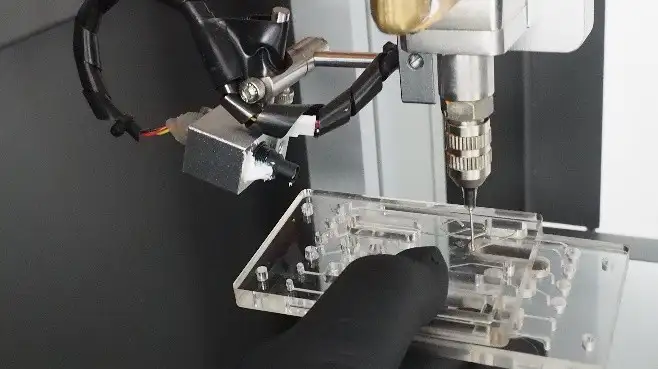
Design and process adjustments are expected before the actual build. During the assembly, it is crucial to have jigs and fixtures, particularly if the design involves a multilayer alignment and/or integration of OTS parts. In a complex cartridge, a computer controlled adhesive dispenser and microscope camera for alignment are usually required for indexing and quality control monitoring.
7. Clear and verifiable quality control process is a must
Strong quality control criteria for parts and the assembly process are critical. To set criteria for inspection, a microfluidic testing plan is required. In this plan, test parameters must be identified, and the acceptance threshold set. Clear and strict criteria will ensure functionality and repeatability of the cartridge build.
The basic test procedures to be employed often include pressure decay, fluid flow test, airflow test and detailed visual inspections. These tests are non-destructive and may be run without the use of actual reagents. During assembly of the initial unit, it is a good practice to perform a sequential operational test for each assembly process step to check each step before proceeding to the next. This can help identify and isolate assembly quality issues, thereby saving time, effort and material.
8. Assess the assembly process transferability to high volume production
Prototyping at small volume is the logical way to test assumptions and the performance of a device design. However, as the development progresses, there is a need for more units to be tested, particularly during the integration of the assay, and in determining the operational parameters of the overall system. For mid volume, injection molding or hot embossing will be most applicable. On the other hand, for large volume, injection molding, roll-to-roll, hot embossing with automated assembly will be the preferred choice. Hence, the device design must take into consideration intended volume and accommodate the appropriate manufacturing method.
Reliable Microfluidic Devices Are Engineered, Not Improvised
Microfluidic device product development is a multi-faceted process. It involves many elements and subsystems. Translating an assay protocol to a microfluidic format requires careful planning and experience during the design and implementation phases.
Following design rules and guidelines will greatly improve the likelihood of successful microfluidic device development. During the design process, a full understanding of the device requirements and critical assay parameters is essential to produce the desired device functionality.
A proof-of-concept prototype is not the final device, it is intended to de-risk basic technical issues. These issues may include assay reagents interaction, assay step-by-step execution, cartridge materials, features to be included in the cartridge, detection mechanism(s), assembly and so on. Methodical mitigation of these issues will save effort, time, and cost during the iterative development process.
Developing a microfluidic device for a target application requires a lot of effort, time, and resources. Ensuring success relies heavily on the implementation of a reliable manufacturing process. Employing the support of an experienced development partner is invaluable to facilitate the design and manufacturing implementation.
In the end, the goal is to produce a reliable, repeatable, and functional microfluidic device to enable clinical testing and ultimately the timely release of the product to the market.
References
- https://www.globenewswire.com/news-release/2022/05/03/2434405/0/en/Microfluidics-Market-Growth-Trends-COVID-19-Impact-and-Forecasts-2022-2027.html
- Ren K, Zhou J, Wu H. (2013) Materials for microfluidic chip fabrication. Acc Chem Res. 46(11):2396-406. doi: 10.1021/ar300314s. Epub 2013 Jun 11. PMID: 24245999.
- Munshi AS, Chen C, Townsend AD, Martin RS. (2018). Use of 3D Printing and Modular Microfluidics to Integrate Cell Culture, Injections and Electrochemical Analysis. Anal Methods. 21;10(27):3364-3374. Epub 2018 Jun 26. PMID: 30923580; PMCID: PMC6433419.
- Scott SM, Ali Z. (2021). Fabrication Methods for Microfluidic Devices: An Overview. Micromachines ;12(3):319. doi: 10.3390/mi12030319. PMID: 33803689; PMCID: PMC8002879. doi: 10.3390/ mi12030319
- Kangning Ren, Jianhua Zhou, and Hongkai Wu, (2013). Materials for Microfluidic Chip Fabrication, Accounts of Chemical Research 2013 46 (11), 2396-2406 DOI: 10.1021/ar300314s
- Niculescu AG, Chircov C, Bîrcă AC, Grumezescu AM. (2011). Fabrication and Applications of Microfluidic Devices: A Review. Int J Mol Sci.;22(4):2011. doi: 10.3390/ijms22042011. PMID: 33670545; PMCID: PMC7921936. https://www.ncbi.nlm.nih.gov/pmc/articles/PMC7921936/
- Gale, Bruce & Jafek, Alexander & Lambert, Christopher & Goenner, Brady & Moghimifam, Hossein & Nze, Ugochukwu & Kamarapu, Suraj. (2018). A Review of Current Methods in Microfluidic Device Fabrication and Future Commercialization Prospects. Inventions. 3. 60. 10.3390/inventions3030060.
- Neil Convery, Nikolaj Gadegaard (2019). 30 years of microfluidics, Micro and Nano Engineering, Volume 2, Pages 76-91, ISSN 2590-0072, https://doi.org/10.1016/j.mne.2019.01.003.
- Xue Han,Yonghui Zhang,Jingkun Tian,Tiange Wu,Zongwen Li,Fei Xing,Shenggui Fu (2021). Polymer-based microfluidic devices: A comprehensive review on preparation and applications. Polymer Engineering and Science. https://doi.org/10.1002/pen.25831
Building a Microfluidic Device? Download the Free eGuide.
Your Microfluidic Device Questions, Answered
What makes microfluidic device development different from other medical device development?
Microfluidic devices must be manufactured with extreme precision at sub-microliter scales, requiring an interdisciplinary team spanning assay development, materials science, fluidics, optics, and sensors. Commercial production is still emerging, and most devices require highly repeatable processes that are difficult to achieve without structured development methodology.
What materials are most commonly used in microfluidic device fabrication?
PDMS is the most widely used material due to its ease of fabrication and low cost, making it popular in research settings. Thermoplastics such as polycarbonate and PMMA are preferred for commercial-scale production because of their optical clarity, compatibility with injection molding, and lower per-unit cost at volume.
How do I choose between off-the-shelf and custom-built components?
Off-the-shelf components can accelerate development and reduce cost, but each one added to a cartridge introduces a potential failure mode. The general rule is to keep OTS components to the minimum required and explore whether custom cartridge design can eliminate the need for them altogether.
What manufacturing method is best for scaling up a microfluidic device?
It depends on the production volume. Micro-machining and 3D printing are well suited to early prototyping, while injection molding and hot embossing are preferred for mid-to-high volume production due to their repeatability, precision, and lower per-unit cost at scale.
When should regulatory strategy be considered in microfluidic device development?
From the start. The intended use of the device determines the regulatory pathway, and that pathway directly influences design decisions, testing requirements, and submission timelines. Waiting until the device is developed to address regulatory strategy is a common and costly mistake.
Lorenzo Gutierrez is a former StarFish Medical Microfluidic Manager. He provides consultation work for medical devices and biotech product development. Lorenzo has extensive experience translating point-of-care assays to microfluidic cartridges. His portfolio includes developing microfluidic devices, instruments for analytes detection, assay integration, and commercialization.
Related Resources

Nick and Nigel breaks down what actually goes into the cost of getting a sterilized device into a user’s hands, and why up to 30% of costs can sit in places most teams don’t plan for.

Theranostics combines diagnosis and therapy into a single targeting system, using one ligand to attach to two different radioactive payloads, one for imaging and one for treatment. It represents a significant shift in how cancer is being identified and treated. But the theranostics delivery workflow tells a different story.

Most medical devices were designed for clinical settings, not the patients and caregivers who increasingly rely on them at home. Here’s what good home-use device design actually requires.

How do you measure comfort in medical device design? Explore the tools, scales, and study design principles that turn a subjective experience into actionable design data.