PCBA Bring-Up in Medical Device Prototypes
TL;DR
- Success in PCBA bring-up rarely happens by chance, it depends on preparation.
- Design for testability before fabrication.
- Prep firmware, fixtures, and tools while boards are in production.
- Inspect thoroughly before power-on to avoid damage.
- Use a structured test matrix to validate systematically.
Bringing up a new printed circuit board assembly (PCBA) for a medical device is both exciting and high-stakes. The design effort that went into schematics, component selection, and layout only pays off if the first assembled units power up and perform as intended. Success at this stage rarely happens by chance.
When bring-up goes poorly, the consequences ripple outward: delays in verification, wasted prototypes, and loss of confidence in the design. Avoiding these pitfalls requires preparation, methodical testing, and the right infrastructure to catch issues early.
This article outlines practical steps you can take before, during, and after receiving your first fully assembled PCBA to increase the likelihood of a smooth bring-up. Whether working independently or within a larger team, these practices shorten debug cycles, prevent costly mistakes, and create a foundation for repeatable, scalable testing in medical device development.
Design for Testability in Medical Device PCBAs
Before submitting your board for fabrication and assembly, take time to think through how you will test it. This step is often overlooked, yet it directly impacts the speed and reliability of bring-up.
Ask yourself:
- How will I inject signals or monitor key circuit behaviors?
- Are there test points for power rails, analog nodes, or digital I/Os?
- Have I included any special connectors or headers to make testing easier?
- Is there a place for a serial number?
At minimum, well-labeled and accessible test points are essential. For traceability, adding serial numbers is highly recommended. Many board houses apply these in silkscreen if you specify location and format.
Also, capture your test strategy early, before the design is finalized. A spreadsheet is a great place to jot down test cases, software and hardware requirements, and notes for future revisions. Documenting this upfront helps ensure that features needed for testing are included in the design.
Preparing to Test While Your PCBA Is in Production
While your boards are being fabricated and assembled, use the time to prepare your testing infrastructure.
Here are a few high-impact activities:
- Write standalone firmware modules to validate specific peripherals (e.g. ADCs, motors, or sensors).
- Build custom test cables or fixtures, such as loopback cables for UART/SPI or motor pigtails for stepper drivers.
- Create test scripts or simple GUI tools if needed.
These efforts make it easier to isolate and verify functionality without needing the full product to be complete. Testing with simple setups first avoids introducing too many variables.
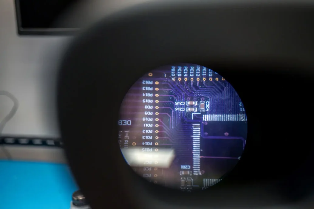
First Checks When Your PCBA Arrives
Unboxing your assembled boards is exciting, but resist the urge to plug them in right away. Even with reputable suppliers, misplacements or soldering errors can occur. A cautious first inspection reduces the risk of damaging critical components.
First, visually inspect the board:
- Are all components populated correctly?
- Are any pads shorted or left unconnected?
- Are polarized components (diodes, electrolytics, ICs) installed in the right orientation?
Once confident in the assembly, power up carefully, ideally using a current-limited bench supply. Monitor current draw and watch for unexpected behavior. If everything looks good, begin testing features.
Using a Test Matrix for Systematic PCBA Bring-Up
Now it is time to put your plan into action. Start by validating power rails, as these are the foundation for everything else.
Typical power testing tools include:
- Digital multimeters
- Oscilloscopes
- Electronic loads
- Power rail probes (if available)
- Thermal cameras (for detecting hot spots in the board that could be a symptom of a defect)
Once the power systems work as expected, move on to higher-level functions. Reference your test matrix to systematically evaluate each subsystem. Logging bugs, unexpected behaviors, and partial passes helps improve future revisions and supports clear communication with your team.
Conclusion
In medical device development, a disciplined bring-up process is not optional. Planning for testability, preparing tools and infrastructure, and following a structured approach ensure that the first prototypes yield insights instead of setbacks. Each step taken with rigor reduces risk, accelerates timelines, and strengthens the foundation for later verification and manufacturing.
By treating bring-up as a deliberate, repeatable practice, development teams turn a high-risk milestone into a reliable pathway toward safe, effective devices for patients.
Mike Ganzert is an Electronics Engineer at Starfish Medical. He received his Bachelor’s of Applied Science in Electrical Engineering from UBC Okanagan in 2021, with a focus in medical devices.
Images: Adobe Stock
Related Resource

Medical device teams developing embedded and cross-platform GUIs can accelerate delivery without compromising usability or validation by choosing the right framework early and designing for performance, portability, and maintainability.
Compute demands on “the edge”, like embedded sensors or remote devices. have grown significantly as AI has moved from experimentation to deployment. Medical devices are pushing more of their AI functionality onto edge hardware.

Medical device cleaning is more complex than it seems. In this Bio Break episode, Nick and Nigel unpack what really goes into cleaning medical devices and why it cannot be treated like a simple wipe-down process.
This blog reviews the main families of optical detectors and the major technologies in those families.